Clutch Slave/Master Rebuild/Replace and Troubleshoot.
The first clutch problem many encounter is with the clutch slave unit. Symptoms can include difficulty shifting, missing fluid in the clutch reservoir, fluid leaking inside the protective boot, a fluid puddle on the ground after parking, or the need to pump the clutch pedal to enable shifting gears. If not losing fluid and pedal is weak or spongy could just be some air in the system or a leaking seal. Suggest a bleed and fluid change first and work from there if needed.
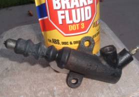
Interesting observation is that many owners go for years without ever checking the clutch fluid. The reservoir holds about 2 ounces when filled to the full line. Suddenly they have no clutch, no fluid in the reservoir, and the fluid is missing or collected in the protective boot. At this point is no reason to jump to the conclusion that is in need of immediate repair/replacement. In most cases all it may need is good bleed and fluid change to last for a few more years. For a quick roadside emergency repair clutch fluid is the same Dot-3 used for the brakes. It may be possible to siphon a little fluid from the brake reservoir in an emergency stranding caused by low clutch fluid. A simple narrow straw works fine for transfer of small amounts of fluid by capping one end with finger.
If a component is faulty, is your decision to replace with new parts, purchase remanufactured units, or rebuild them yourself. In any event the bleeding process, tools needed, and the removal and install of both the clutch master and slave are the same. Will start with these two pictures and can be looked at again if needed.
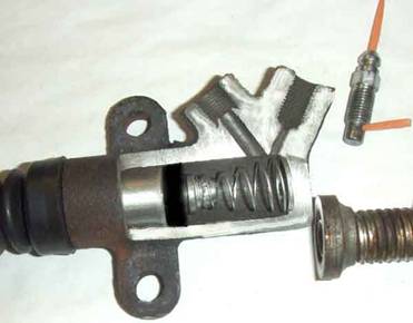 The Slave. Showing a pix with part of the slave unit cut away to view the valve
and parts. It is possible to add a slave
rebuild kit without removing the unit but seems a bad idea once you note the
amount of dirt and crud packed at the rear of the bore. Takes about two minutes to change then add a
little more time to bleed the system.
Start with the little baggie trick shown later to help hinder loss of
fluid when the slave piston is removed.
Push the release arm rearward enough to remove the plunger and boot,
slightly press the clutch pedal to slide the piston back and grab with fingers
to remove, then install the rebuild kit and bleed. Again, seems very bad idea unless is a
roadside emergency. If you look inside
the bore will find the bleeder opening and feed opening to be about 1/8” apart
and at the very top of the bore. The
crud remains inside unless the unit is removed and bore is cleaned. A simple method is shown a bit later.
The Slave. Showing a pix with part of the slave unit cut away to view the valve
and parts. It is possible to add a slave
rebuild kit without removing the unit but seems a bad idea once you note the
amount of dirt and crud packed at the rear of the bore. Takes about two minutes to change then add a
little more time to bleed the system.
Start with the little baggie trick shown later to help hinder loss of
fluid when the slave piston is removed.
Push the release arm rearward enough to remove the plunger and boot,
slightly press the clutch pedal to slide the piston back and grab with fingers
to remove, then install the rebuild kit and bleed. Again, seems very bad idea unless is a
roadside emergency. If you look inside
the bore will find the bleeder opening and feed opening to be about 1/8” apart
and at the very top of the bore. The
crud remains inside unless the unit is removed and bore is cleaned. A simple method is shown a bit later.
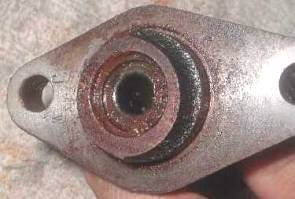
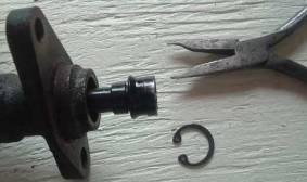
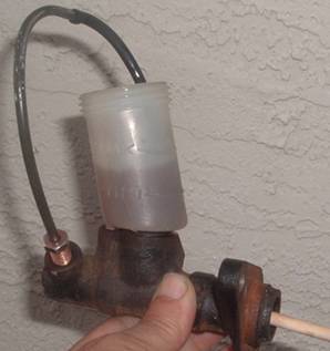
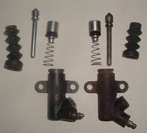
Also note the fitting (centermost) and see how the hydraulic feed line is attached. It seals differently than the bleeder valve shown towards the right. Missing is the small metal bearing that seals the small opening into the unit. It is pressed in place and sealed with the blunt tip on the valve. This could be significant on certain years and explained later on this page, and why using flare wrench should be used. Pieces of orange toothpick show the opening locations inside the bleeder valve. Don’t lose the bearing. !!! I have 3 old units left over from various tech sessions and not one bearing! Shown near the bottom of this page are two different types of bleeder valves. Notice also the black seal on the piston. It is a one way seal that allows the fluid to push the piston forward and not leak. The seal is the usually the first component to fail in the hydraulics system. The second is probably the protective boot at the front. If the boot is damaged or torn, moisture will cause rust in the front of the bore and wear down the seal faster.
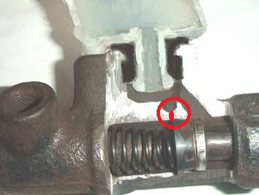
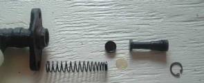
The Master. Here an old master was partially sliced to show the inside. The reservoir cup and sealing grommet is also sliced to show position of the parts and how everything works. To get the unit to work the front of the unit down to the slave must be primed. Multiple different ways to do this “bleeding” are discussed later. The primary seal is cup shaped and fits on the end of the spring and acts as a one way valve. The secondary seal on the opposite end of the master piston keeps fluid from dribbling out the back of the bore into the driver’s foot well. Probably about the last seal to fail since it is not under any pressure. I drew the short red line (inside the red circle) to denote a small hole that was removed by my band saw when slicing the unit open. It is directly in front of the primary seal. Appears it was added to allow for any minor expansion or contraction of the working fluid caused by heat. As the piston moves forward of less than 1/64” the primary seal nullifies the hole. I named this as “Hydraulic Free play” for lack of a better term, and when this is added to the clutch pedal free play it accounts for the total free play in the system.
In a good working system, the fluid in the reservoir should never change practical detectable levels during normal operation. Over time, the two ounces held in the reservoir may go down pending such things as small leaks. Some owners have gone 10 years or more without ever checking the fluid level. Understanding how this works may also help with diagnosing a bad slave from a bad master which again is covered a bit later.
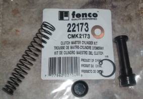
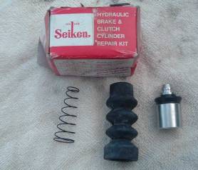 The clutch slave rebuild kit runs about $5-$10
as an on shelf item in many auto parts stores, or can obtain one from local
Mazda Dealership. The kit contains a
spring, boot, piston and seal.
The clutch slave rebuild kit runs about $5-$10
as an on shelf item in many auto parts stores, or can obtain one from local
Mazda Dealership. The kit contains a
spring, boot, piston and seal.
Will remove the old slave unit and decide if the rebuild kit is sufficient or if the entire unit needs replacing. Only need 10 –15 minutes to do either if you have a few tools and done them before.
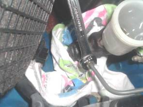
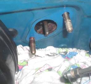
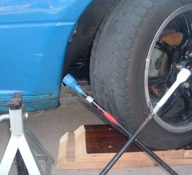 If
peering behind the canted wheel can see the slave unit inside the engine
compartment. On my homemade ramps so I
can slide my floor jack underneath and put front on jack stands, then remove
the wheel. If only changing/bleeding the
fluid, the small ramps alone are enough.
Can also do it with the stock jack, but extra caution is needed such as
chocking the remaining wheels and as a minimum a jack stand and the wheel
underneath for safety. Will be working
with arms inside the wheel well. Could
do it as is on the boards, but makes a poor photo opportunity.
If
peering behind the canted wheel can see the slave unit inside the engine
compartment. On my homemade ramps so I
can slide my floor jack underneath and put front on jack stands, then remove
the wheel. If only changing/bleeding the
fluid, the small ramps alone are enough.
Can also do it with the stock jack, but extra caution is needed such as
chocking the remaining wheels and as a minimum a jack stand and the wheel
underneath for safety. Will be working
with arms inside the wheel well. Could
do it as is on the boards, but makes a poor photo opportunity.
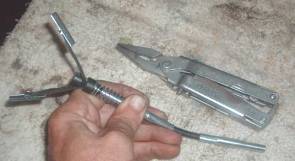
Put my 4-way in pix as item of interest. Have multiple vehicles in different colors so a little shot of paint or tape saves a little fumble time when working on the wheels to locate the proper lug size.
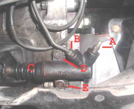 Slave
unit. Right (A) is the bleeder
valve. Loosen with an 8 mm box/flare
wrench to bleed all the old Dot 3 out. A
¼” diameter hunk of flexible tubing forced over the nipple and fed into an old
jar will save a big mess in driveway.
Give the clutch pedal a few pumps to get the fluid started and allow
gravity to finish. Process covered a bit
later. If completely removing the
bleeder valve for any reason, use caution not to lose the tiny ball bearing
inside.
Slave
unit. Right (A) is the bleeder
valve. Loosen with an 8 mm box/flare
wrench to bleed all the old Dot 3 out. A
¼” diameter hunk of flexible tubing forced over the nipple and fed into an old
jar will save a big mess in driveway.
Give the clutch pedal a few pumps to get the fluid started and allow
gravity to finish. Process covered a bit
later. If completely removing the
bleeder valve for any reason, use caution not to lose the tiny ball bearing
inside.
The hydraulic line (B) should be removed using a 10 mm flare wrench. Have a rag ready to clean up a few drops of fluid. When replacing the line, suggest starting it with fingers to avoid cross threading, and then tighten it after unit is installed and bolted back in place. Cross threading that fitting is a good way to ruin your day! The protective boot is C.
Both mounting bolts are 12 mm. Use a box wrench from underneath for the lower bolt (E) and a 10”-12” socket extension for the top (D) bolt. Due to working room will find it difficult to do any other way.
Optional step. Can use a Mighty-Vac tool, food baster, or similar too to remove fluid from the reservoir. Can just as easily ignore this step and allow the old fluid to bleed through the system. Not too concerned about doing it, since planning to run some extra clean fluid through the system when finished. If concerned with priming or bench bleeding needed, can look at another suggestion contained with the last picture in Testing the Master. I suggest leaving the old fluid alone if just replacing or rebuilding the slave unit as is less chance of losing the prime in the master.
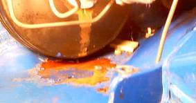 This
old picture shows what happens if Dot 3 remains on a painted surface. It was caused by an unrelated seal failure on
the brake fluid reservoir. It took a
fair amount of sanding, some primer and paint to repair damage. The visible damage in picture is only about
1/3rd of the damaged area.
This
old picture shows what happens if Dot 3 remains on a painted surface. It was caused by an unrelated seal failure on
the brake fluid reservoir. It took a
fair amount of sanding, some primer and paint to repair damage. The visible damage in picture is only about
1/3rd of the damaged area.
Suggest if even reasonably certain that you did not get any fluid on the paint, take a few moments and hose down/wash when finished.
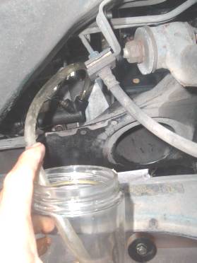 This
is a posed picture of the jar and tube over the loosened bleeder valve.
This
is a posed picture of the jar and tube over the loosened bleeder valve.
Bleeding. When replacing the fluid or if just bleeding out the system, prefer a helper for a few minutes to work the clutch pedal while I loosen slightly and retighten the bleeder valve. Same method used for bleeding the brakes with exception of different pedals and different valves. Fill the fluid reservoir. Have helper push the pedal. Open valve until pedal reaches the floor and hold it down. Close bleeder valve and release pedal. Refill reservoir after every couple of pump cycles. Repeat as needed until all air and bubbles are pushed out of system and fluid running through system is clean. To speed the process, suggest twisting the bleeder valve with fingers to open and closed between pump cycles with the hose in place. Use wrench for the last couple of pumps. There are some inexpensive vacuum bleeders available, but in many cases they will suck air from around the bleeder valve threads, sometimes difficult to make a tight seal on the bleeder valve, are awkward to use, messy, and time consuming. Pressure bleeding tools also work if you can get a good seal over the reservoir. Gravity bleeding, vacuum bleeding, and pressure bleeding I would rate as “Better than nothing.” There is no turbulence from the moving pistons to force much accumulated crud from the bores. With those methods, are only slowly meandering fluid past the primary seal, down the hydraulic line, and travels about 1/8th of an inch skimming the top of the slave bore and out the bleeder valve.
Additional Bleeding Methods:
Gravity. May or may not work, mostly pending if the slave or master was removed, or if the lines were drained. Is a very slow process (if it works) since the only weight to pull fluid past the primary seal is contained in the tiny feed line. Also note the fluid must defy gravity and climb the hydraulic line that is located higher than the reservoir. Additional drawbacks I see aside from the time involved is that it only dilutes the old fluid without any turbulence in the system to flush out crud.
Vacuum. There are multiple different devices available. They typically work by creating a vacuum on the slave bleeder valve, then sucking fluid out of the reservoir, past the master primary seal, and out the system via the bleeder valve. Has the same drawback as the gravity bleed plus adding the possibility of sucking some air in around the bleeder valve threads and also creating a bigger mess.
Pressure. Usually, a device that fits over or in the reservoir to push fluid through the system and out the opened slave bleeder valve. Drawback again is it causes little turbulence in the system to completely flush out any accumulated crud.
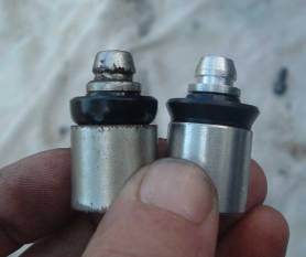
 Speed and/or Solo Bleed Devices. The image on right shows the basic
principle on how they work. The one on
top shown in the C clamp is simulating how it would look installed as a
tightened slave bleeder valve. When
loosened a bit, it will function as a one-way valve. With the valve opened a turn or so and the
clutch pedal is pressed, the fluid pressure forces the tip back against the
spring permitting the fluid to flow out the end of the valve. When the clutch pedal is released, the spring
tip seals the opening in the slave. The
spring in the front bore of the master pushes the piston back, causing a light
vacuum condition in the working fluid, then draws fresh fluid into the system
from the reservoir.
Speed and/or Solo Bleed Devices. The image on right shows the basic
principle on how they work. The one on
top shown in the C clamp is simulating how it would look installed as a
tightened slave bleeder valve. When
loosened a bit, it will function as a one-way valve. With the valve opened a turn or so and the
clutch pedal is pressed, the fluid pressure forces the tip back against the
spring permitting the fluid to flow out the end of the valve. When the clutch pedal is released, the spring
tip seals the opening in the slave. The
spring in the front bore of the master pushes the piston back, causing a light
vacuum condition in the working fluid, then draws fresh fluid into the system
from the reservoir.
Additional bleeding note. If you change the master or completely drain the fluid, may find that just pumping the pedal without a helper or additional device will not get fluid thru the system. Is clearer just by looking at the hydraulic line and note how the line climbs the firewall, over the top of the reservoir, then across the firewall and eventually down to the slave. Until that line is filled to add some resistance and help from gravity, will probably be there a long time just pushing fluid and air back and forth. More detail in bench bleeding section.
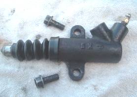 The
slave is removed. At this point can tip
the unit over and work the plunger by hand and get a little more dirty fluid
and some crud out. Will take it apart
and determine if it should be replaced or rebuilt. If the rubber boot is torn or missing for an
undetermined time would probably replace the unit.
The
slave is removed. At this point can tip
the unit over and work the plunger by hand and get a little more dirty fluid
and some crud out. Will take it apart
and determine if it should be replaced or rebuilt. If the rubber boot is torn or missing for an
undetermined time would probably replace the unit.
The rubber boot is still intact and serviceable. The boot holds the plunger in place on the cylinder by snugly fitting over the grooves on the plunger and slave body. There were a few mild rust spots on the metal rod, but the rod is not in contact with the fluid inside the bore.
 If
the piston and spring have not fallen out yet can just tap on the body to make
it fall out, or push little finger inside and catch the hole in back of the
piston and pull it out. Another option
is a little compressed air.
If
the piston and spring have not fallen out yet can just tap on the body to make
it fall out, or push little finger inside and catch the hole in back of the
piston and pull it out. Another option
is a little compressed air.
Once removed, can feel inside for any pitting and see if it is still serviceable for a rebuild kit. There was a fair amount of crud remaining at bottom, but a good rinse and sloshing with mineral spirits and artist brush got it clean. Have never discovered any rust inside the fluid areas or on the internal spring. Can only guess that is because of a lack of oxygen in the sealed system.
Was more of a slight visual discoloration and not felt with fingers. Do not think honing was needed but did it later anyway. No rust or corrosion was noted anywhere inside the bore or on the spring.
All parts shown are stock original with about 165 K miles on them, with exception of the seal on the piston. The seal has about 55 K miles of use, and the only part replaced during a previous rebuild.
 Old
piston on left, new at right. Can see
how the spring chewed up the end of the piston a little. That does not hurt anything.
Old
piston on left, new at right. Can see
how the spring chewed up the end of the piston a little. That does not hurt anything.
Most prominent is how the old seal was slightly hardened and flattened out over time. The seal had no chunks missing or scratches or rough edges. If I knew a part number for that seal, would probably be about the only part needed for a slave rebuild.
When pushing the piston will take a little fiddling to ensure the seal is still facing toward the valve. Get a wrinkle or kink and it will not slide against the spring properly and leak fluid. Found it easy to use thumbnail to start tucking it in place and rotate the piston around a little.
 After
an internal lubing with DOT 3, assemble, and push the rod in and check to see
if it moves evenly and spring pushes it out just as smoothly. Don’t let it snap out or will probably need
to take it apart and seat the piston again.
After
an internal lubing with DOT 3, assemble, and push the rod in and check to see
if it moves evenly and spring pushes it out just as smoothly. Don’t let it snap out or will probably need
to take it apart and seat the piston again.
To make bleeding easier suggest filling the chamber first with Dot 3 to eliminate as much air as possible. A hollow straw with your finger over the end works very well. Two more things to repeat: Ensure the small bearing is under the bleeder valve (pending unit) and start a few threads on the hydraulic fitting prior to bolting it in place. When it was removed, the line had to be bent slightly and the last thing you want is to cross thread the fitting. Install the unit and bleed as described earlier.
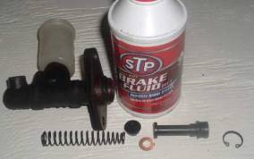
Clutch Master Rebuild Kit.
 Picked this kit up at DiscountAuto for $11 as
a stocked item. Not having any problems
with the master after 170 K miles, just rebuilding it for something to do and a
photo opportunity.
Picked this kit up at DiscountAuto for $11 as
a stocked item. Not having any problems
with the master after 170 K miles, just rebuilding it for something to do and a
photo opportunity.
Only variation noted between the OEM and these kit parts were the piston on the secondary seal assembly and the spacer on the stock unit were plastic, and on the Chinese rebuild kit they were both metal.
Odd observation. No differences were detected between the old and replacement primary seals. Suppose I was expecting to see some wear.
After draining the fluid, a 10 mm flare wrench was used to remove the hydraulic fitting. Hint: When replacing the line again, start the threading with fingers prior to bolting the master back on the firewall. The line will flex a little as needed, just don’t cross-thread the fitting!
The two nuts securing the unit to the firewall are 12 mm. No clearance problems with using a deep well and ratchet. A couple of turns is probably all that is needed to break it loose, then easier to turn the deep well with fingers.
We will dribble a little used Dot 3, so have an old rag in place.
 In
about 2 minutes the assembly is removed.
In
about 2 minutes the assembly is removed.
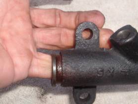
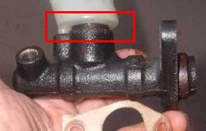
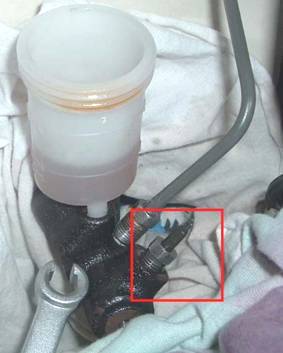
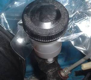
The boxed area is where I would first expect a leaking master. It is a rubber type grommet that force fits the fluid reservoir to the housing. If needing to change it at some date only need to drain the fluid and pry off the cup. Easier said than done. That grommet appears to be the main source of the black crud in the system, rather than from any of the seals on the pistons. It is not the same material as used in the seals.
 With
the unit removed, save and reuse the white seal. Not much to see with it removed except the
need to clean the engine bay! The
protruding rod in the center is part of the mechanical linkage from the clutch
pedal. It pushes on the piston to make
the hydraulic system work. There was a
small smear of fluid on the mechanical push rod but nothing serious. . Notice the edge of the carpet padding inside
the cavity.
With
the unit removed, save and reuse the white seal. Not much to see with it removed except the
need to clean the engine bay! The
protruding rod in the center is part of the mechanical linkage from the clutch
pedal. It pushes on the piston to make
the hydraulic system work. There was a
small smear of fluid on the mechanical push rod but nothing serious. . Notice the edge of the carpet padding inside
the cavity.
Speculate if the problem is a loss of fluid and no evidence of fluid spills anywhere else, problem could be the secondary seal in the master. Suggest pulling back the carpet/padding behind the clutch pedal and check for the missing fluid. Would also indicate the primary seal is probably in need of replacement, If the primary seal is bad, may see a small rise and fall of the reservoir fluid an the clutch pedal is pressed and released. Will show both of these seals later and will be able to see how they work.
 Difficult
to see in pix, but there is a snap ring there that must be removed first. Some rust accumulation on the exterior after
16 years, but again no rust detected inside the bore or on the spring.
Difficult
to see in pix, but there is a snap ring there that must be removed first. Some rust accumulation on the exterior after
16 years, but again no rust detected inside the bore or on the spring.
There was a fair amount of crud inside the cylinder at the opposite end. Little more mineral spirits and artist brush to get it clean.
Observe how the old parts were removed so the new kit is properly installed. The parts will fit inside but will not work properly in the wrong order. In some instances it may be gummed up inside where all the parts will not fall out. Tap the end on a wooden block and jar it loose or try some compressed air in the hydraulic fitting.
 The
only difference noted in the secondary seal was where the flare is flattened
out inside the bore. The old one was
still working fine even flattened out as shown.
New piston on left and is metal.
OEM piston was plastic. Appears
the purpose of the secondary seal is to keep the piston straight in the bore,
and to prevent the fluid from draining out of the reservoir and into the
driver’s foot well. It is not under any fluid
pressure.
The
only difference noted in the secondary seal was where the flare is flattened
out inside the bore. The old one was
still working fine even flattened out as shown.
New piston on left and is metal.
OEM piston was plastic. Appears
the purpose of the secondary seal is to keep the piston straight in the bore,
and to prevent the fluid from draining out of the reservoir and into the
driver’s foot well. It is not under any fluid
pressure.
Picked up this hone for $10 mostly for Show ‘N Tell and will use it for other projects. As shown it had a flexible shaft section so a hand drill could be used. Has an adjustable spring to vary the pressure. Did not like the way it fit inside the bore, so bent the arms a bit so the stones fit flush with even pressure inside the small bore. My opinion is if the bores are pitted inside where the seals slide … pitch the unit out and replace with a new one.
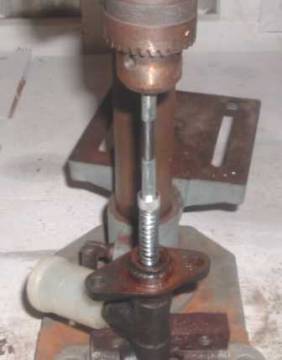 I
used the hone in a cheapo drill press.
Let me run a slower constant speed with better ability to slide the hone
up and down in a straight line.
I
used the hone in a cheapo drill press.
Let me run a slower constant speed with better ability to slide the hone
up and down in a straight line.
In my opinion, the master and slave really did not need to be honed. There were some slight marks inside (more of a discoloration) both seen with a strong light, but unable to capture with the digital camera. All I really did was erase those marks with a light and short honing. If pitting is discovered inside the bore surfaces, suggest not even using a hone or rebuild kit and just replace the entire unit.
Both the master and slave push the piston relatively perpendicular into the valve and not like an engine piston with some lateral movement to make the cylinder out of round.
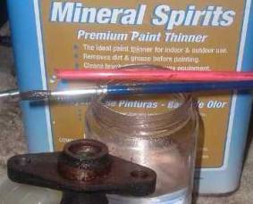 Next
step was to clean the inside of the bore.
My favorite solvent is mineral spirits, and a little paintbrush worked
well inside the bore. The little piece
of soda straw worked well for blowing some crud out and drying.
Next
step was to clean the inside of the bore.
My favorite solvent is mineral spirits, and a little paintbrush worked
well inside the bore. The little piece
of soda straw worked well for blowing some crud out and drying.
When removing the spring and primary seal it may be stuck inside and unable to lightly shake or tap out. Compressed air can be used to push it out. I just used the little piece of straw and blew thru the removed hydraulic fitting. Little caution needed to avoid launching the little parts into neverland. The straw can also be used to push the piston from the slave unit in the same manner
 Ready
to assemble with replacement rebuild kit.
Give all the parts a generous lube with your favorite Dot 3. The 4 parts before the snap ring will fit in
forward or backwards or in any order.
Unit will not work though if not properly installed. If the unit has been cleaned well or using a
new or reman unit, suggest pouring some fluid inside the bore first then
working piston by hand to prime the valve.
Again, start a few threads on the
fitting prior to bolting in place to avoid cross threading.
Ready
to assemble with replacement rebuild kit.
Give all the parts a generous lube with your favorite Dot 3. The 4 parts before the snap ring will fit in
forward or backwards or in any order.
Unit will not work though if not properly installed. If the unit has been cleaned well or using a
new or reman unit, suggest pouring some fluid inside the bore first then
working piston by hand to prime the valve.
Again, start a few threads on the
fitting prior to bolting in place to avoid cross threading.
The primary seal is cup shaped and fits over the tapered end of the spring. A leaking primary seal could be a cause for needing to pump the clutch pedal to enable shifting and not show symptoms of fluid loss. That is not inclusive either as the same applies to the slave unit.
 That
is about everything to it. Requires some
fumbling to squeeze the secondary seal in properly. Used my fingernail to properly guide in the
seal lip.. When assembled, used a short
wood dowel to work the piston to ensure it pushed in smoothly and the spring
pushed it back to the snap ring smoothly.
That
is about everything to it. Requires some
fumbling to squeeze the secondary seal in properly. Used my fingernail to properly guide in the
seal lip.. When assembled, used a short
wood dowel to work the piston to ensure it pushed in smoothly and the spring
pushed it back to the snap ring smoothly.
Install the unit, fill with fluid, and bleed system as described earlier.
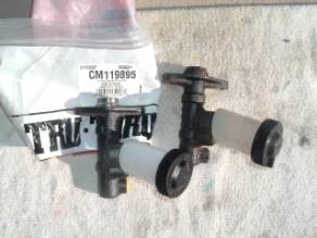
 Pictured
is a new made in
Pictured
is a new made in
The Miata forum is well studded with claims of failures of new OEM units, aftermarket units, remans, and rebuild kits. Will let you decide which route to take.
 This
is a new
This
is a new
The problem she was having was sometimes needing to pump the clutch a few times to build up pressure, and then would only hold the pressure for a few seconds. No severe leaks were detected and she stated she topped off the fluid every few months. I told her it should take less than 45 minutes for a first time user to replace both and be back on the road. It took her nearly 1.5 hours. Her most difficult part of the job was breaking the slave bolts loose. I let her do it herself with minor intervention.
Since the old units had no core charge I requested the old parts. Took the old master to AutoZone and tried to get a plug for the hydraulic fitting. Later ground them down to show the cutaway views.
Testing the Master.
No proper plugs were found on the shelf, but rummaged around behind the counter and found this unknown vehicle brake line part for about $3. Cut about a 1 ½” piece off one end, crimped the cut end closed, then silver brazed inside the remaining tube. This should make a nice tight plug with no air space inside. It worked fine. Suspect a short metric bolt for 30 cents would have worked as well. Unknown if the missing flare at the end would be needed to make a proper seal.
 With
the master still installed in the Miata the hydraulic line was removed. The new plug was substituted. Installed it slowly to ensure there was no
air trapped at the plug. Most of the
fluid spill will be from that little dangling segment, so use rags to absorb
the fluid. Should be less than 1/4 ounce
of spilled fluid to be absorbed.
With
the master still installed in the Miata the hydraulic line was removed. The new plug was substituted. Installed it slowly to ensure there was no
air trapped at the plug. Most of the
fluid spill will be from that little dangling segment, so use rags to absorb
the fluid. Should be less than 1/4 ounce
of spilled fluid to be absorbed.
The clutch pedal will now feel tight like the brake pedal. The clutch pedal goes down slightly until the free play is removed and become firm well above the floor pan. If it still stays firm after a minute of medium pressure, the master should be good, and the problem is either the slave or in the line/fittings to the slave. When finished, will still need to bleed the system, but no priming is needed. Remember the hydraulic line is in 3 pieces so if the master is good does mean the slave is faulty. Would check those connections next to see if you find any traces of fluid on those line segments or any kinks in the line are detected.
A second method is bit harder to see and less accurate. If the problem is losing pressure after being pumped up, have a helper work the clutch while you observe the fluid level. If the fluid level rises while losing pressure then is most probable the fluid is leaking past the primary seal and back into the reservoir. If pumped up a second time, the fluid level should drop slightly. During normal operation with all working properly the fluid level should not change. May note a small amount of turbulence since the fluid is moving underneath but is fluid between the primary and secondary seals.
 The
remaining piece of brake line and opposite fitting made a bench bleeding
tool. A little hunk of vacuum line on
the end allows it to extend to the bottom of the fluid reservoir. Used a wooden dowel to work the valve. Something like a pencil end or small
screwdriver works as well. If wishing to
install the unit with fluid prior to replacement, pull the vacuum line off, use
the sandwich baggie, replace the reservoir cap, then swap for the hydraulic
line and bolt back in place. The biggest
benefit I can find from using one either with master installed or removed is
giving a better cleaning of the small passages under the reservoir. Can pump it several times to darken the
fluid, then dump the fluid out and repeat as needed. That black grommet that holds the reservoir
to the cylinder is the primary source for the black fluid, so after a simple
typical bleeding many will find the reservoir fluid black again after a short
time. There is really no reason to
remove the master to do this. Can just
pump the clutch pedal several times with the tool in place.
The
remaining piece of brake line and opposite fitting made a bench bleeding
tool. A little hunk of vacuum line on
the end allows it to extend to the bottom of the fluid reservoir. Used a wooden dowel to work the valve. Something like a pencil end or small
screwdriver works as well. If wishing to
install the unit with fluid prior to replacement, pull the vacuum line off, use
the sandwich baggie, replace the reservoir cap, then swap for the hydraulic
line and bolt back in place. The biggest
benefit I can find from using one either with master installed or removed is
giving a better cleaning of the small passages under the reservoir. Can pump it several times to darken the
fluid, then dump the fluid out and repeat as needed. That black grommet that holds the reservoir
to the cylinder is the primary source for the black fluid, so after a simple
typical bleeding many will find the reservoir fluid black again after a short
time. There is really no reason to
remove the master to do this. Can just
pump the clutch pedal several times with the tool in place.
 Another
little trick. If desired to lose a
minimal amount of fluid from the reservoir, use a little plastic lunch baggie
to seal the top of the reservoir and secure it with the cap. The OEM cap is vented to atmosphere and this
will hinder the gravity siphoning flow of fluid. May also me handy if working with the slave
unit where you prefer not to lose the prime in the master. Will need to remove the baggie prior to
testing the master or when finished with the slave prior to the final bleed.
Another
little trick. If desired to lose a
minimal amount of fluid from the reservoir, use a little plastic lunch baggie
to seal the top of the reservoir and secure it with the cap. The OEM cap is vented to atmosphere and this
will hinder the gravity siphoning flow of fluid. May also me handy if working with the slave
unit where you prefer not to lose the prime in the master. Will need to remove the baggie prior to
testing the master or when finished with the slave prior to the final bleed.
Addition Methods to Assist Bleeding or Initial Priming.
 This
section is only designed for those having problems with priming the entire
system prior to finishing the two man bleed method. If stuck and unable to get fluid flowing by
other means, no expensive novelty tools are needed as is just a simple
mechanical method to make fluid flow past the primary seal and into the lines
and down to the slave unit. The primary
seal acts as a 1-way valve.
This
section is only designed for those having problems with priming the entire
system prior to finishing the two man bleed method. If stuck and unable to get fluid flowing by
other means, no expensive novelty tools are needed as is just a simple
mechanical method to make fluid flow past the primary seal and into the lines
and down to the slave unit. The primary
seal acts as a 1-way valve.
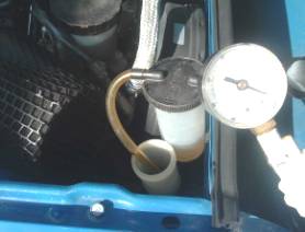
Can come up with dozens of methods to do it but here are a few ideas from common house hold items. On left is a simple needle valve for inflating a sports ball. The lid insert is removed and the needle valve is pushed thru the existing vent hole. To make it pressurize the reservoir, fill reservoir, open the bleeder valve about ½ turn on the slave unit, replace cap and use any bicycle or tire pump. Add fluid as needed and watch for the fluid flowing from the slave bleeder valve. At this point suggest finishing the job with the two person bleeding method. Image is the cap from an OEM reservoir with the insert under the cap removed. This may not work with an aftermarket unit since one I examined had a different size vent.
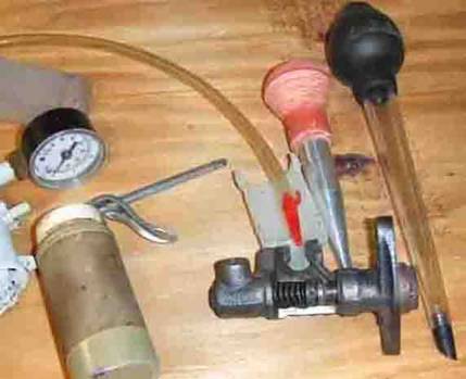 Here
are a few more common things that will work without pressurizing the entire
reservoir. Notice the hole in the bottom
of the reservoir from the one I sliced in half.
The red tip shown attached to the line from a Mity-Vac is the valve from
many air pumps and used to inflate beach toys and rafts. Just need something to push down over the
hole to make it seal well enough to force fluids inside. The pump type oil can and many basters will
work. The one on the right is for show
and tell since the opening is too large on this one to make a good seal.
Here
are a few more common things that will work without pressurizing the entire
reservoir. Notice the hole in the bottom
of the reservoir from the one I sliced in half.
The red tip shown attached to the line from a Mity-Vac is the valve from
many air pumps and used to inflate beach toys and rafts. Just need something to push down over the
hole to make it seal well enough to force fluids inside. The pump type oil can and many basters will
work. The one on the right is for show
and tell since the opening is too large on this one to make a good seal.
To make these work, will need to half fill the reservoir, crack open the slave bleeder, and fill the tool with Dot 3 and force it into the master and down to the slave unit. Could also try a squeeze bottle with a long tip, but may be difficult to find one that fits snugly in the reservoir. Once fluid is flowing from the slave bleeder valve suggest finishing with the two person bleeding method.
There are additional methods that work. Should find several more ideas around the house and garage. Really only need a small amount to pressure to make the fluid flow past the primary seal
Special note for 89/90 Miatas.
If ordering units from a local auto parts store may find two different parts listed for both the master and the slave. One stores computer stated that starting at VIN 11970 and higher there was a change from a 5/8” bore to a ¾” bore. The parts counter worker will probably not know that and only sees two different part numbers but does not know why. One local store listed two parts for the ’90 and ’91. My Miata has a VIN of 125985 and was assembled in October, so was well into the ¾” bore range. Suggest if running into the problem of not knowing which is which, and the VIN is greater than 11970, just have them look up the parts for a ’92 and take those. Have not had the opportunity to examine the early master and cannot verify the bore size. However, the master bore diameter from VIN greater than 11970 is still 5/8”. The slave bore and master bores are different diameters. Hoping someone can clear this up.
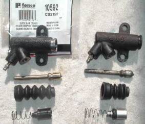
 A
poster Eunos Aerodyne, sent me this slave unit he ordered from a dealership for
his VIN of below 111970. The box was
included and indicates it is a genuine Seiken part and made in Japan. It is on the left, and the unit on the right
is an OEM from a’90 and well over the 11170 VIN. Immediate difference noted is a different
angle for the bleeder valve, which should not matter. Both have a ¾” bore and same depth. The push rod on one is a bit longer but is
insignificant since the hydraulics is self adjusting. The protective boots are a bit different, but
that does not matter either.
A
poster Eunos Aerodyne, sent me this slave unit he ordered from a dealership for
his VIN of below 111970. The box was
included and indicates it is a genuine Seiken part and made in Japan. It is on the left, and the unit on the right
is an OEM from a’90 and well over the 11170 VIN. Immediate difference noted is a different
angle for the bleeder valve, which should not matter. Both have a ¾” bore and same depth. The push rod on one is a bit longer but is
insignificant since the hydraulics is self adjusting. The protective boots are a bit different, but
that does not matter either.
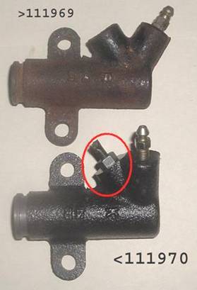 Unfortunately
it leaked badly around the circled area.
Used my little clutch master testing tool and threaded it all the way
into the hydraulic line opening. It
would not reach the bottom and still had approximately 3/16” of free play in
the flared fluid line. No way could that
make a good seal. With the plug in the
top unit, it formed a tight seal and still had approximately 3/16” of remaining
threads showing. 2d problem was that the
end of the feed line is concave and makes a snug fit in the upper unit against
a convex protrusion at the bottom. In
the lower unit, the bottom is also concave.
Seems even if the surface is ground down about ½” or if using a longer
threaded coupling nut, would still not obtain a good seal. If you do have a ’90 with the early VIN, just
order the later VIN for the replacement.
No additional adjustments or modifications are needed.
Unfortunately
it leaked badly around the circled area.
Used my little clutch master testing tool and threaded it all the way
into the hydraulic line opening. It
would not reach the bottom and still had approximately 3/16” of free play in
the flared fluid line. No way could that
make a good seal. With the plug in the
top unit, it formed a tight seal and still had approximately 3/16” of remaining
threads showing. 2d problem was that the
end of the feed line is concave and makes a snug fit in the upper unit against
a convex protrusion at the bottom. In
the lower unit, the bottom is also concave.
Seems even if the surface is ground down about ½” or if using a longer
threaded coupling nut, would still not obtain a good seal. If you do have a ’90 with the early VIN, just
order the later VIN for the replacement.
No additional adjustments or modifications are needed.
This is my guesswork on what happened. Because of the conflict in different parts books and including a post about an odd looking master installed, suggest the original master and slave had a 5/8” bore and later changed to a ¾” bore with VIN >111969. Noticed that none of the parts books offer a rebuild kit for <111970 and only replacement units. Replacement units came with the ¾” bore but Mazda messed up by not making it with a compatible hydraulic fitting. Not too much stink about it since involved relatively few Miata owners. If this can be confirmed or proven wrong please advise and will make changes as needed.
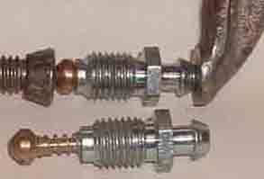
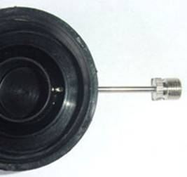
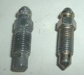 As
an insignificant item of interest, the OEM bleeder valve has a blunt end. Can barely see a small mark on the bottom
center where it presses down on a small metal ball bearing to seal the valve. If removing the bleeder valve for any reason
suggest not losing the little bearing! A few posted about finding a small bearing
inside the bore. Can only guess the
valve was tightened too far and pushed the bearing inside. That does not seem plausible due to the
larger size of the bearing and a smaller hole.
Unknown. The replacement unit had
a bubble end and no bearing.
As
an insignificant item of interest, the OEM bleeder valve has a blunt end. Can barely see a small mark on the bottom
center where it presses down on a small metal ball bearing to seal the valve. If removing the bleeder valve for any reason
suggest not losing the little bearing! A few posted about finding a small bearing
inside the bore. Can only guess the
valve was tightened too far and pushed the bearing inside. That does not seem plausible due to the
larger size of the bearing and a smaller hole.
Unknown. The replacement unit had
a bubble end and no bearing.
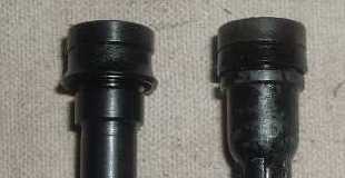
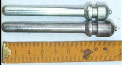 Another
image and comment. Shown are two
different push rods from the slave units.
The length on either is insignificant since the hydraulic system is self
adjusting. Meaning with a shorter push
rod there is more fluid in the slave bore.
Since the release arm pushes back the slave piston, the amount of fluid
will vary. The small mild spring inside
the slave bore helps hold the piston and pushrod against the release arm.
Another
image and comment. Shown are two
different push rods from the slave units.
The length on either is insignificant since the hydraulic system is self
adjusting. Meaning with a shorter push
rod there is more fluid in the slave bore.
Since the release arm pushes back the slave piston, the amount of fluid
will vary. The small mild spring inside
the slave bore helps hold the piston and pushrod against the release arm.
Mechanical Pedal Adjustments.
Unable to take a picture that makes sense so best idea is to assume a very uncomfortable position under the dash and look up at the mechanical linkage. Both mechanical adjustments should be clear if needed by working the pedal with your hand.
There are two different mechanical adjustments that should be checked or made for the hydraulic system to work properly. The first adjustment is the pedal height. Want 7” (plus or minus about 1/8”) between the slanted portion of the floor pan to the top center of the pedal. Look up under the dash and locate the pedal stop, and the awkward lock bolt. Disconnect the Interlock first prior to rotation of the stop, and attach the plug again when finished. Loosen the lock bolt and adjust the pedal stop as needed and tighten the lock bolt.
Next step is to adjust the lash (free play) in the pedal. The lash is the amount the pedal moves from its topmost position until it starts moving the pushrod. About ¼” is fine plus or minus not more than 1/8”. Loosen the locknut, then twist the pushrod to remove excess slack or tighten as needed.