 About
3 ½ years later was time for an engine swap.
Had nothing to do with the turbo, but from allowing a broken nitrous
fitting to get sucked into the intake.
It did not digest well in the valves and combustion chamber.
About
3 ½ years later was time for an engine swap.
Had nothing to do with the turbo, but from allowing a broken nitrous
fitting to get sucked into the intake.
It did not digest well in the valves and combustion chamber.
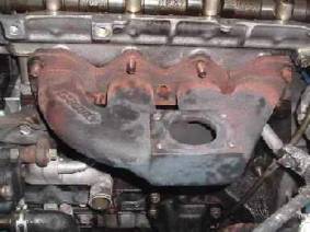
All 4 of these bolts and 3 on the DP sheared off flush. The 3 relief cuts closed meaning I had to pry and beat it off the head. Replacing the studs on the replacement engine so stud damage was not an issue. At this point was not sure how to get it back on the replacement engine without damaging the new studs.
There are several good pages on engine replacement, so only adding a few different observations.
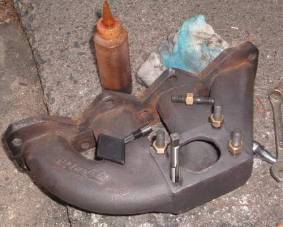 Drilled
all 7 of the broken studs out then tapped all 8 holes for 3/8 16 studs and used
copper nuts. One little problem was
breaking the tip on the tap on the last hole.
Fortunately. Was able to
hammer it through the manifold.
Drilled and tapped larger and used a helicoil.
Drilled
all 7 of the broken studs out then tapped all 8 holes for 3/8 16 studs and used
copper nuts. One little problem was
breaking the tip on the tap on the last hole.
Fortunately. Was able to
hammer it through the manifold.
Drilled and tapped larger and used a helicoil.
Strongly suggest not even attempting to do this without a drill press, level, and some good clamps on the drill press. Also suggest not even trying an EZ-Out on those small bolts. Also had to drill out the turbo and downpipe holes to fit the larger studs. They were all too long but a few moments on a bench grinder fixed that. Caution on drilling the gasket as is laminated metal. Sandwiched it between two scraps of thin board.
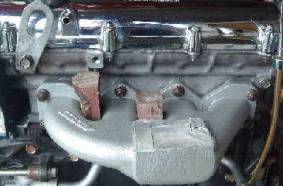 Little
ahead of myself here, but my Chevy buddies snickered
and told me to use a manifold spreader to get the manifold back on. I first elongated the holes a bit then
hammered some oak wedges between the runners.
Got a little more space between the runners, but was enough to replace
the manifold without damaging the new studs.
Little
ahead of myself here, but my Chevy buddies snickered
and told me to use a manifold spreader to get the manifold back on. I first elongated the holes a bit then
hammered some oak wedges between the runners.
Got a little more space between the runners, but was enough to replace
the manifold without damaging the new studs.
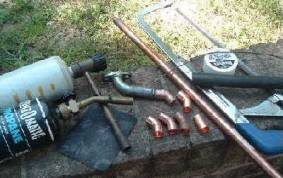 Never
liked the way the oil return made the steep bend to fit down to the oil pan
tap. Experimented with
brazing in some copper fittings using 45’ bends. Eventually ripped this all out, sawed about 1
½” from the turbo fitting, then brazed the fittings together differently for a
better return to the oil pan. When
finished, only needed about $5.50 for all of the copper fittings and the oil
pan tap, and used about 10” of the supplied hose.
Never
liked the way the oil return made the steep bend to fit down to the oil pan
tap. Experimented with
brazing in some copper fittings using 45’ bends. Eventually ripped this all out, sawed about 1
½” from the turbo fitting, then brazed the fittings together differently for a
better return to the oil pan. When
finished, only needed about $5.50 for all of the copper fittings and the oil
pan tap, and used about 10” of the supplied hose.
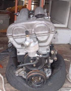 Replacement plant from a wrecked ’93 with about 100K miles on it. Was easy to work on sitting
in back of my step-van. Replaced
it with my water pump (about 30 K miles) , new coolant
O-Rings and gaskets (4), but swapped out the tensioner
pulley since mine old one had a little wobble to it.
Replacement plant from a wrecked ’93 with about 100K miles on it. Was easy to work on sitting
in back of my step-van. Replaced
it with my water pump (about 30 K miles) , new coolant
O-Rings and gaskets (4), but swapped out the tensioner
pulley since mine old one had a little wobble to it.
May as well change the timing belt, all 3 of the front seals, CAS O-Ring and cam cover gasket.
Have some new replacement intake manifold and exhaust manifold gaskets, so will match them up and mate to the ports. On this engine, the exhaust ports on the head were fairly clean, but all of the intake ports needed a fair amount of grinding. My old intake manifold also had quite a bit of rough casting inside, so that took a fair bit of sanding inside to smooth it all out.
With all the replacement parts mentioned plus the new clutch, pressure plate, bearings, rear seal, and set of motor mounts came out to about $310. Labor involved was a little blood and some bad words.
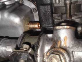
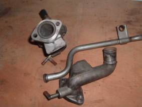 Tossing
the pix out since many do not know these seals exist. At upper left is a view of the thermostat
housing where it attaches to the head.
If that seal leaks, coolant can run down behind the timing belt and dust
covers and make it appear the water pump is leaking. It is about a 70 cent replacement from many
auto parts stores. Need to rummage
around in their O Ring bin(s). Don’t
recall the sizes.
Tossing
the pix out since many do not know these seals exist. At upper left is a view of the thermostat
housing where it attaches to the head.
If that seal leaks, coolant can run down behind the timing belt and dust
covers and make it appear the water pump is leaking. It is about a 70 cent replacement from many
auto parts stores. Need to rummage
around in their O Ring bin(s). Don’t
recall the sizes.
The second one is the small fat O Ring at the end of the metal tube from the heater core. Takes a little grunt to pop the tube out, and a little lube helps pop it back in place. Only aware of a couple failures here and usually in conjunction with exhaust manifold removals.
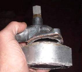 Was
not sure what this spacer was for under the thermostat cap so asked on the Miata Net.
Apparently it was from some sort of aftermarket CAI that required
elevating the top hose. Figured for the
65 cents for an extra gasket could use it and add a few extra ounces of
coolant. After installation the folded
prop rod hit the top hose. Prop rod was
easy enough to bend to make it fit properly.
A few minutes of polishing made it worthy to install on my Miata.
Was
not sure what this spacer was for under the thermostat cap so asked on the Miata Net.
Apparently it was from some sort of aftermarket CAI that required
elevating the top hose. Figured for the
65 cents for an extra gasket could use it and add a few extra ounces of
coolant. After installation the folded
prop rod hit the top hose. Prop rod was
easy enough to bend to make it fit properly.
A few minutes of polishing made it worthy to install on my Miata.
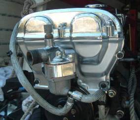 Looks better now.
Manifolds are finished, but will put those on after the engine is installed. When on the hoist, can reseal the oil pan and
tap for the oil return. Also need some
parts to finish replacing the clutch, add a new pilot and release bearing,
rebuild the slave, and add new rear oil seals.
Need to wait on those when old engine is pulled.
Looks better now.
Manifolds are finished, but will put those on after the engine is installed. When on the hoist, can reseal the oil pan and
tap for the oil return. Also need some
parts to finish replacing the clutch, add a new pilot and release bearing,
rebuild the slave, and add new rear oil seals.
Need to wait on those when old engine is pulled.
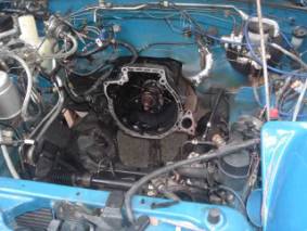 The
obligatory cavity shot. Later dropped
the transmission, assembled on the ground and installed it back as a single
unit. The PS and AC units were tied back
out of the way. No loss of freon or fluids.
The
obligatory cavity shot. Later dropped
the transmission, assembled on the ground and installed it back as a single
unit. The PS and AC units were tied back
out of the way. No loss of freon or fluids.
Observation: The intake manifold was a bit awkward to remove with the engine installed, but simplifies the starter removal/replacement. Suppose could have just pulled the head for simplicity but would have lost the hoist hooks. No plans on doing this too many times so no best suggestions. My own self-inflicted dummy attack was in not removing the bracket that secures the coil of hydraulic clutch line. It bent it fairly bad. When engine was pulled., it made some kinks and awkward bends. Thought I fixed it, but it showed it’s ugly head over a year later when starting to have some clutch problems.
One problem noted was alignment of the engine mounts. Loosely fit them in place one side at a time with engine on hoist, then secured properly when in place.
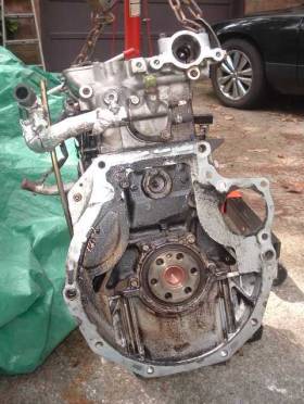 Out with the old.
Even the rear seal appeared to be in good shape after 160 K miles and
about 120K of those were with turbo.
Out with the old.
Even the rear seal appeared to be in good shape after 160 K miles and
about 120K of those were with turbo.
Also replaced 9 of the coolant hoses. Did not replace the capped and unused coolant nipple. Didn’t think to look forward enough and order one. Hope that does not bite me down the road a bit!
As a filler for this larger picture, adding a reminder to always cut old hoses off from the heater core. They will be stuck on there tight and is easy to mash the thin heat core fittings. The hose partially hidden is the most problematic for Greddy users. It is very close to the downpipe. I cut about 1 ½” from the end that attaches to the head and about ¾” from the end to the heat core. Twisted it around a little so have a good space away from the Greddy downpipe. No problems with it hitting the BBowser heat shield. If doing this, extra caution is needed to ensure there are no kinks or anything to restrict the lines. That is the main artery for coolant flow from the back of the engine to the water pump.
The final step was wrapping them in heat blanket and using a
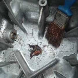
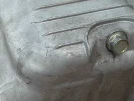 Think
may have encountered an alley apple somewhere.
After cleaning up the oil pan, noticed a spider web maze of fractures. Hard to see in picture, but they covered
about ¼ of the oil pan. Were clearly
visible inside and outside. Was driving
on borrowed time here! Have another oil
pan so the ragman got another free donation.
Think
may have encountered an alley apple somewhere.
After cleaning up the oil pan, noticed a spider web maze of fractures. Hard to see in picture, but they covered
about ¼ of the oil pan. Were clearly
visible inside and outside. Was driving
on borrowed time here! Have another oil
pan so the ragman got another free donation.
 Sure
is a lot easier to tap the oil pan while removed! Is a bigger blessing if you have AC. The brass fitting used was a 5/8” X ½” from
Home Depot. The part is from Watts (A-493) and cost $1.92. If you don’t have a tap, suggest walking over
to the tool section and getting one. Tap
needed is a ½” X 14 NPT. Drill bit
needed is 23/32”. Will not matter if the hose barb 5/8” (HD) or ¾” (NAPA). Get a cheapo since will probably be a one
time use and the aluminum case is not too hard.
Don’t complicate things! If
unsure about the tap or fitting size there is a rack somewhere in the store to
screw those things into to check for proper size! Center of hole should be 2” down from the
lower lip at the shallowest smooth portion.
Sure
is a lot easier to tap the oil pan while removed! Is a bigger blessing if you have AC. The brass fitting used was a 5/8” X ½” from
Home Depot. The part is from Watts (A-493) and cost $1.92. If you don’t have a tap, suggest walking over
to the tool section and getting one. Tap
needed is a ½” X 14 NPT. Drill bit
needed is 23/32”. Will not matter if the hose barb 5/8” (HD) or ¾” (NAPA). Get a cheapo since will probably be a one
time use and the aluminum case is not too hard.
Don’t complicate things! If
unsure about the tap or fitting size there is a rack somewhere in the store to
screw those things into to check for proper size! Center of hole should be 2” down from the
lower lip at the shallowest smooth portion.
I cut the threaded portion down to about ¾” long to ensure it would not hit the oil pickup tube. Could have gone with a ¾” barb but that is really snug and didn’t see one there. If unsure of the hose barb size, take a little piece of hose in store with you.
 Looking
up from the front driver’s side. Not
much space to work with tools especially if you have AC and PS which mine
has. The first one I did was with the
pan installed. This photo does not show
all the obstructions.
Looking
up from the front driver’s side. Not
much space to work with tools especially if you have AC and PS which mine
has. The first one I did was with the
pan installed. This photo does not show
all the obstructions.
How I did it. Drain the old oil and save it for a quick rinse when finished. Reversed the hose on a shop vacuum and taped it to the oil fill. Positive pressure in the oil pan. As soon as you punch thru will get a face full of oil spray and metal shavings. Wear some goggles. Added some tape around the drill bit and tap to serve as a depth gauge to ensure did not go more than ¾” deep. Go much deeper will hit the windage tray or much worse … punch a hole in the oil pick-up line. Big problems then. Grease the bit and tap and work slowly, back out and clean off any metal shavings a few times. Since did not have any small enough power tools to drill the hole, I started with a stubby unibit at a slight angle for a pilot hole. Twisted the 23/32” drill bit by hand to round out the hole, and get it straight and the proper diameter. Not as difficult as you may think working with aluminum. Cut down the threaded portion of the fitting down to about ¾” and JB Weld in place. Flush out the system good, can use the old oil first, then follow with some mineral spirits, kerosene, or waste a few tins of dino.
 Looking
inside the deep end of my old cracked oil pan, remember will never be able to
get all the crud out. Will still retain
about 4 ounces of fluid and many other particles that settle to the bottom. Most of that was hard brittle crud and old
gasket sealer that managed to work it’s way to the bottom. At left is the oil drain hole. With the steel sleeve insert and angle, will
not drain the very bottom. Remaining but
hard to see is some fine aluminum grit, with about the consistency and amount
of a small pinch of fine sand. The point
here is to use caution not to get any metal bits in the pan to begin with.
Looking
inside the deep end of my old cracked oil pan, remember will never be able to
get all the crud out. Will still retain
about 4 ounces of fluid and many other particles that settle to the bottom. Most of that was hard brittle crud and old
gasket sealer that managed to work it’s way to the bottom. At left is the oil drain hole. With the steel sleeve insert and angle, will
not drain the very bottom. Remaining but
hard to see is some fine aluminum grit, with about the consistency and amount
of a small pinch of fine sand. The point
here is to use caution not to get any metal bits in the pan to begin with.
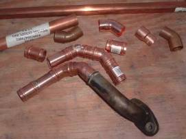 Not
liking the big sweeping curve of the supplied rubberized hose for the supplied
turbo oil drain fitting, I brazed some little copper fittings together. They are standard copper ½” water pipe repair
fittings, available at Home Depot for about 21 cents to 50 cents each. Just play with the fittings to find something
that is optimal. The lower piece is
bolted to the turbo and the piece just above it is the piece that wraps around
the AC bracket.
Not
liking the big sweeping curve of the supplied rubberized hose for the supplied
turbo oil drain fitting, I brazed some little copper fittings together. They are standard copper ½” water pipe repair
fittings, available at Home Depot for about 21 cents to 50 cents each. Just play with the fittings to find something
that is optimal. The lower piece is
bolted to the turbo and the piece just above it is the piece that wraps around
the AC bracket.
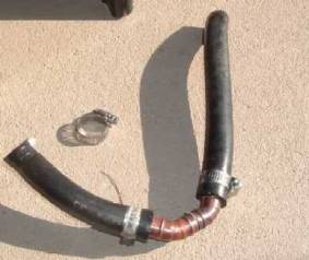 Hose
segments are installed and ready to install.
A little bit of heat helped perform the hoses so there is no stress on
any of the connections. It now snakes
from the turbo to the oil pan fitting without any sharp bends hitting anything
else. Depending on AC or PS, could have
a different configuration.
Hose
segments are installed and ready to install.
A little bit of heat helped perform the hoses so there is no stress on
any of the connections. It now snakes
from the turbo to the oil pan fitting without any sharp bends hitting anything
else. Depending on AC or PS, could have
a different configuration.
 View
from the bottom under the AC. At top
right can see a portion of the AC line which increases the fun of getting tools
and hands in there to work.
View
from the bottom under the AC. At top
right can see a portion of the AC line which increases the fun of getting tools
and hands in there to work.
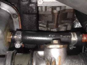
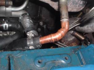 From
the top, can see how it fits routed down to the oil pan from the turbo. As far as the hard silver rod used, it held
fine for two years with no leak at any of the braze points. I just changed it for a little more optimal
configuration. Another option could have
been to cut about 1” from the tube so it sits a bit farther away from the
ledge.
From
the top, can see how it fits routed down to the oil pan from the turbo. As far as the hard silver rod used, it held
fine for two years with no leak at any of the braze points. I just changed it for a little more optimal
configuration. Another option could have
been to cut about 1” from the tube so it sits a bit farther away from the
ledge.
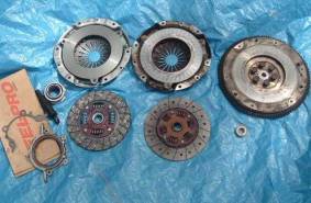 This
is the Value Line clutch from Excedy (left). Is the basic (under $100) 5 piece kit
available from a Miata.Net vendor. If
you have the clutch replaced by a dealership, they will probably give you the Excedy anyway. The
kit also came with the alignment tool, release bearing, and pilot bearing. The old release bearing appeared fine, but
the old pilot bearing felt a bit “notchy” when
twisting with fingers. Was sent the
wrong oil seal, but no biggie either as was an on shelf item at the local
AutoZone.
This
is the Value Line clutch from Excedy (left). Is the basic (under $100) 5 piece kit
available from a Miata.Net vendor. If
you have the clutch replaced by a dealership, they will probably give you the Excedy anyway. The
kit also came with the alignment tool, release bearing, and pilot bearing. The old release bearing appeared fine, but
the old pilot bearing felt a bit “notchy” when
twisting with fingers. Was sent the
wrong oil seal, but no biggie either as was an on shelf item at the local
AutoZone.
Flywheel appeared fine. Just burnished it a bit with some fine emery. Could have lightened it a few pounds, but seemed like a bad idea with a turbo
 Here
was the worse worn spot. Remember again
it is the original stock unit with 160K, with about 120 K miles of those with 8
PSI boost and an occasional hint of mist.
Here
was the worse worn spot. Remember again
it is the original stock unit with 160K, with about 120 K miles of those with 8
PSI boost and an occasional hint of mist.
Could have squeezed more out of it, maybe even reach 200K miles. A new disk runs about $60, but little point in waiting longer because of labor involved. No differences were noticed in performance or feel between the old OEM and the replacement Excedy. No additional adjustments were needed.
The $5 slave rebuild kit was still working fine after 50 K miles so just bled it out and replaced the clutch fluid.
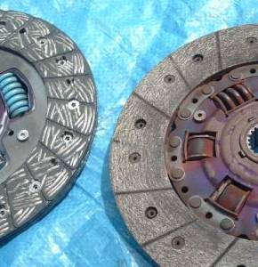
 Just
a mini shot to show the new Excedy (left) and worn
OEM (right) thickness. No immediate
danger of hitting the rivets.
Just
a mini shot to show the new Excedy (left) and worn
OEM (right) thickness. No immediate
danger of hitting the rivets.
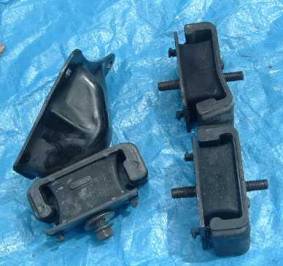 Replaced
the old shock mounts also (right).
Noticed the steel plate on one was bent.
Again, unable to detect any driving difference between the old and new.
Replaced
the old shock mounts also (right).
Noticed the steel plate on one was bent.
Again, unable to detect any driving difference between the old and new.
The picture as shown gives the illusion that the old ones were also compressed. I measured them and only detected about 1/32” difference. Is just the way the picture was taken that makes the old ones look like they were severely compressed.