There are some very good write-ups on installing the Greddy kit, so trying to add some things that are a little different. Nothing really complicated about installing the basic kit. If you have adequate tools and worked on vehicles should take about 3 hours to install. Remember I have had a turbo in and out of my Miata 7 times and assisted with install of other forced induction (FI) systems. Only tuning needed is adjusting the ignition timing. We are going to add a little more time by reading the instructions, making inventory, and possibly modifying some of the parts prior to the actual install. Pix were taken with a cheapo net camera and inept page-designer. No beauty, but hope has some function. Add a few tests to make and a few other problems that may be encountered during install.
Since already had a boost/vacuum gauge installed, was relatively certain the engine was in good shape. Could see a vacuum test performed every time I drove and no anomalies were detected that would indicate problems with such things as vacuum leaks, valves, rings, head gasket, or exhaust restrictions.
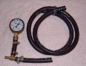
Prior to installing any FI system, suggest making a vacuum test, fuel system test, and compression test.
 Still,
a good time to run a test of the stock fuel pump and stock FPR. Can make this mechanical gauge set up
complete for about $20 at NAPA. A
pressure gauge (air tank) will run about $8, and need a hunk of 5/16” fuel
line, a brass “T” and a few hose clamps. After the final turbo install, can splice the longer piece between the
gauge and “T” gauge. Can then tape the
gauge to outside of window for a temporary road test under boost after complete
installation.
Still,
a good time to run a test of the stock fuel pump and stock FPR. Can make this mechanical gauge set up
complete for about $20 at NAPA. A
pressure gauge (air tank) will run about $8, and need a hunk of 5/16” fuel
line, a brass “T” and a few hose clamps. After the final turbo install, can splice the longer piece between the
gauge and “T” gauge. Can then tape the
gauge to outside of window for a temporary road test under boost after complete
installation.
For several years used a $20 electronic oil pressure gauge with sender spliced into the fuel IN line. That was just as accurate and could safely mount the gauge permanently inside the cockpit. Reading up to 100 PSI of fuel pressure was more than enough for my system.
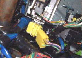 Before
adding the fuel pressure gauge for testing, need to depressurize the fuel
system. Reach under the dash (driver’s
footwell} with engine at idle and unplug this clunky yellow (Circuit Opening
Relay) plug. When engine stalls, replace
the plug and switch engine key of OFF. Fuel rail is depressurized up to the stock FPR. Reason for doing this is when you splice in
the fuel pressure gauge, will not spew fuel from the over 30 PSI trapped in the
fuel rail. Will still be small bit of pressure
remaining to produce one small spurt, but fuel can still dribble out from
gravity until the fuel rail is empty.
Before
adding the fuel pressure gauge for testing, need to depressurize the fuel
system. Reach under the dash (driver’s
footwell} with engine at idle and unplug this clunky yellow (Circuit Opening
Relay) plug. When engine stalls, replace
the plug and switch engine key of OFF. Fuel rail is depressurized up to the stock FPR. Reason for doing this is when you splice in
the fuel pressure gauge, will not spew fuel from the over 30 PSI trapped in the
fuel rail. Will still be small bit of pressure
remaining to produce one small spurt, but fuel can still dribble out from
gravity until the fuel rail is empty.
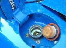 Remove
the gas cap. This will depressurize the
fuel tank and fuel return system behind the stock FPR.
Remove
the gas cap. This will depressurize the
fuel tank and fuel return system behind the stock FPR.
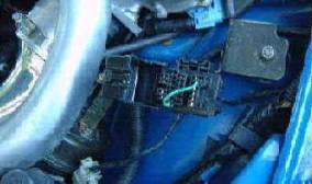 Put
a small shunt between the F/P and GND in the diagnostic test box. This will allow the fuel pump to run when
ignition switched to ON while engine is not running. Don’t turn the key yet until we hook up the fuel gauge. I named this process “Prime Mode” for lack
of a better name. If you try to test
the fuel pump with engine running, once you reach around 60-70 PSI the engine
will enter severe labor and engine stall. That shuts off the fuel pump and cannot finish test.
Put
a small shunt between the F/P and GND in the diagnostic test box. This will allow the fuel pump to run when
ignition switched to ON while engine is not running. Don’t turn the key yet until we hook up the fuel gauge. I named this process “Prime Mode” for lack
of a better name. If you try to test
the fuel pump with engine running, once you reach around 60-70 PSI the engine
will enter severe labor and engine stall. That shuts off the fuel pump and cannot finish test.
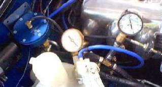
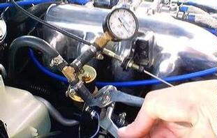 This
picture shows my gauge spliced into the fuel return line. Did it this way to test the fuel pump, with
ignition switched ON (engine not running), pinch the return line closed to read
the maximum available pressure from the fuel pump. From doing this test on at least a dozen different Miatas, they
all produced from 78 to 86 PSI of fuel pressure. That is more then enough pressure for up to 6-maybe 7 PSI boost
from the basic kit. As a good caution,
do not want to run more than 6 PSI without intercooling.. Need to switch the gauge to the fuel IN line
to test the stock FPR. Could have
initially put the gauge on the fuel IN line to save time, but would have used
some padding on channel locks to pinch the fuel return line. With gauge on IN line, pull strap for
diagnostic test box and idle engine. At
idle (21” manifold vacuum) should read between 32-37 PSI. Remove the signal line to the stock FPR to
create a fake manifold pressure at atmosphere. Fuel pressure should jump about 5-10 PSI. Readings will be in range of around 41-45 PSI. Nothing gospel about these pressures, just
my observations from the dozen or so personally tested.
This
picture shows my gauge spliced into the fuel return line. Did it this way to test the fuel pump, with
ignition switched ON (engine not running), pinch the return line closed to read
the maximum available pressure from the fuel pump. From doing this test on at least a dozen different Miatas, they
all produced from 78 to 86 PSI of fuel pressure. That is more then enough pressure for up to 6-maybe 7 PSI boost
from the basic kit. As a good caution,
do not want to run more than 6 PSI without intercooling.. Need to switch the gauge to the fuel IN line
to test the stock FPR. Could have
initially put the gauge on the fuel IN line to save time, but would have used
some padding on channel locks to pinch the fuel return line. With gauge on IN line, pull strap for
diagnostic test box and idle engine. At
idle (21” manifold vacuum) should read between 32-37 PSI. Remove the signal line to the stock FPR to
create a fake manifold pressure at atmosphere. Fuel pressure should jump about 5-10 PSI. Readings will be in range of around 41-45 PSI. Nothing gospel about these pressures, just
my observations from the dozen or so personally tested.
 Compression
test. There is enough information on
the net on how to do this properly so will skip that. The book calls for 192 PSI maximum, and 135 PSI minimum at 3
pops. Book allows 28 PSI difference,
but I prefer a figure of 10 percent. If
a figure is too high may be due to some carbon build-up in combustion
chamber. Can try a simple “water decarbonization”
to see if that helps. If a figure is
too low, suggest going for a little romp and then retesting. May have knocked a bit of carbon loose that
is stuck in the gauge seal or lodged in valve. Proceed with a wet test and leak-down test if needed.
Compression
test. There is enough information on
the net on how to do this properly so will skip that. The book calls for 192 PSI maximum, and 135 PSI minimum at 3
pops. Book allows 28 PSI difference,
but I prefer a figure of 10 percent. If
a figure is too high may be due to some carbon build-up in combustion
chamber. Can try a simple “water decarbonization”
to see if that helps. If a figure is
too low, suggest going for a little romp and then retesting. May have knocked a bit of carbon loose that
is stuck in the gauge seal or lodged in valve. Proceed with a wet test and leak-down test if needed.
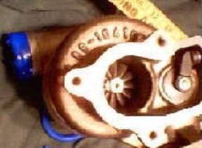
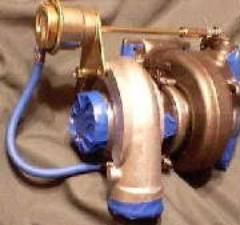 Taped
the openings closed on the turbo. Knew
would be handling it for a while doing other work, so didn’t want to get any
debris inside.
Taped
the openings closed on the turbo. Knew
would be handling it for a while doing other work, so didn’t want to get any
debris inside.
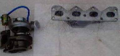 An
early step was checking the mating surfaces to ensure they were all flat. A piece of plate glass worked very
well. The mating surfaces on the turbo
and on the exhaust manifold were well machined flat.
An
early step was checking the mating surfaces to ensure they were all flat. A piece of plate glass worked very
well. The mating surfaces on the turbo
and on the exhaust manifold were well machined flat.
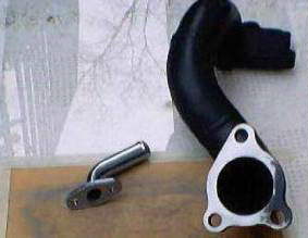 The
flanges on both ends of the exhaust outlet pipe and flange on oil return
fitting were warped, probably from the welding process. Taped a piece of sanding medium to the plate
glass and started rubbing. Wanted them
to match the mating surfaces to avoid stress on the bolts and to provide a
better seal. Can see from the next two
pictures what was removed. The gaskets
at both ends of the pipe matched fine, and no work was needed on the stock
piece back to the cat. Did not hurt
anything to check all the surfaces anyway prior to installing.
The
flanges on both ends of the exhaust outlet pipe and flange on oil return
fitting were warped, probably from the welding process. Taped a piece of sanding medium to the plate
glass and started rubbing. Wanted them
to match the mating surfaces to avoid stress on the bolts and to provide a
better seal. Can see from the next two
pictures what was removed. The gaskets
at both ends of the pipe matched fine, and no work was needed on the stock
piece back to the cat. Did not hurt
anything to check all the surfaces anyway prior to installing.
 The
pipe also had some welding beads inside. Little hard to see from picture but I wanted them out for a less
restrictive exhaust flow. Could not
reach the bead in middle of pipe, so had to settle just for doing both ends.
The
pipe also had some welding beads inside. Little hard to see from picture but I wanted them out for a less
restrictive exhaust flow. Could not
reach the bead in middle of pipe, so had to settle just for doing both ends.
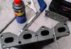 Manifold
cuts. The idea of these cuts cam from
Mr. Bell from BEGI when my BEGI unit cracked between the runners. After welding the other unit I made similar
cuts. Trick is to keep an oiled blade and
cut slow with little pressure. Rush the
job and will eat blades in about 10 seconds and be at it all week rather than
30 minutes. Needed hacksaw as skill saw
would not fit between one of the runners. Could have made more cuts as others have done, but did not see the
need. Maybe my folly will crop up down
the road somewhere. My general attitude
was that if it does crack later, just weld it.
Manifold
cuts. The idea of these cuts cam from
Mr. Bell from BEGI when my BEGI unit cracked between the runners. After welding the other unit I made similar
cuts. Trick is to keep an oiled blade and
cut slow with little pressure. Rush the
job and will eat blades in about 10 seconds and be at it all week rather than
30 minutes. Needed hacksaw as skill saw
would not fit between one of the runners. Could have made more cuts as others have done, but did not see the
need. Maybe my folly will crop up down
the road somewhere. My general attitude
was that if it does crack later, just weld it.
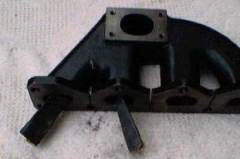 Manifold
was very good inside. Were a few small
nuggets inside so just smoothed them out. Not much to improve for exhaust flow, just wanted them out to avoid any
future possibility of having them go through the turbo. Used a piece of old sanding belt. A regular sheet of sanding medium is not
long enough to do the job.
Manifold
was very good inside. Were a few small
nuggets inside so just smoothed them out. Not much to improve for exhaust flow, just wanted them out to avoid any
future possibility of having them go through the turbo. Used a piece of old sanding belt. A regular sheet of sanding medium is not
long enough to do the job.
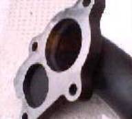
 Examining
the manifold to turbo port, didn’t like the 90’ turn the exhaust made into the
turbo, nor the sharp edges on the flange. Beveled those out. Picture is
poor, but taken before finishing. Should work well enough to show idea.
Examining
the manifold to turbo port, didn’t like the 90’ turn the exhaust made into the
turbo, nor the sharp edges on the flange. Beveled those out. Picture is
poor, but taken before finishing. Should work well enough to show idea.
 This
was the most disturbing part. Can
partially see the fringe marks on the old (laying behind the manifold)
gasket. The marks were from the stock
manifold/head. Looking at both sides
can see where either, the gasket protruded into the manifold, or where the head
and manifold and head did not match. All ports had some areas slightly off and one was off center by
3/16”. Solution was a new $12
gasket. Magic marker worked well on the
new gasket, and an old bottle of white-out worked on the new manifold and
head. Also stuffed a small oil soaked
rag inside the head ports to grind a short way into the head. Could remove the head for a better job, but
saving that for another day. Was a bit
difficult to keep centering the gasket during the several flips back and forth,
so just let it hang straight down and cut the gasket first.
This
was the most disturbing part. Can
partially see the fringe marks on the old (laying behind the manifold)
gasket. The marks were from the stock
manifold/head. Looking at both sides
can see where either, the gasket protruded into the manifold, or where the head
and manifold and head did not match. All ports had some areas slightly off and one was off center by
3/16”. Solution was a new $12
gasket. Magic marker worked well on the
new gasket, and an old bottle of white-out worked on the new manifold and
head. Also stuffed a small oil soaked
rag inside the head ports to grind a short way into the head. Could remove the head for a better job, but
saving that for another day. Was a bit
difficult to keep centering the gasket during the several flips back and forth,
so just let it hang straight down and cut the gasket first.
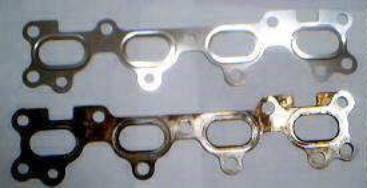 This
may show a little better with new and used gasket set. Can also see black fringe marks on the stock
manifold where it blocked exhaust from the head. That didn’t mean anything since was matching the head with a new
manifold and gasket set.
This
may show a little better with new and used gasket set. Can also see black fringe marks on the stock
manifold where it blocked exhaust from the head. That didn’t mean anything since was matching the head with a new
manifold and gasket set.
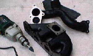 A
couple different small grinding stones on the drill worked well for most of the
grinding done.
A
couple different small grinding stones on the drill worked well for most of the
grinding done.
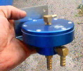
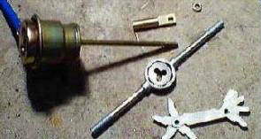 Could
not snug the gate tighter because wished to retain the locking nut to tighten
the fitting securely to the rod. Just
added an extra ¼” of threading and gave enough room. Saw a few other jobs where spacing washers were used, mounting
brackets bent, or extra spring(s) were added. This seemed the best solution. The Greddy instructions clearly state not to tamper with the
wastegate. Can only guess a few
reasons why. If the rod twists in the
can, will ruin it. The supplied system
is set up for about 5 PSI so the supplied AFPR works with the capabilities of
the stock fuel pump. Will make that
your call if you wish to do it.
Could
not snug the gate tighter because wished to retain the locking nut to tighten
the fitting securely to the rod. Just
added an extra ¼” of threading and gave enough room. Saw a few other jobs where spacing washers were used, mounting
brackets bent, or extra spring(s) were added. This seemed the best solution. The Greddy instructions clearly state not to tamper with the
wastegate. Can only guess a few
reasons why. If the rod twists in the
can, will ruin it. The supplied system
is set up for about 5 PSI so the supplied AFPR works with the capabilities of
the stock fuel pump. Will make that
your call if you wish to do it.
 Observation. The exhaust outlet has an ID of 1 7/8”. The supplied pipe is also 1 7/8” ID as well
as the remaining stock exhaust system. No point in adding a larger down pipe unless the remaining system is
equal to or larger all the way to the tail pipe. A bottle neck is still a bottle neck.
Observation. The exhaust outlet has an ID of 1 7/8”. The supplied pipe is also 1 7/8” ID as well
as the remaining stock exhaust system. No point in adding a larger down pipe unless the remaining system is
equal to or larger all the way to the tail pipe. A bottle neck is still a bottle neck.
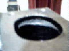
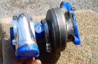
 This
is the Aerodyne I plan on replacing with the Greddy. Don’t see any practical way I can keep the modified airbox, since
it mates directly to the hood scoop. Noticed the brake fluid is a bit low and wondering where it went.
This
is the Aerodyne I plan on replacing with the Greddy. Don’t see any practical way I can keep the modified airbox, since
it mates directly to the hood scoop. Noticed the brake fluid is a bit low and wondering where it went.
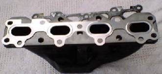
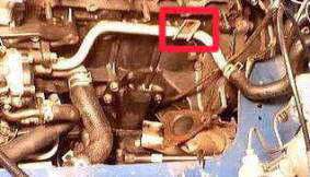 The
highlighted tab may require some grinding on edges to fit on the new
manifold. At this stage, also finished
the manifold matching and checking the exhaust flange. Also wrapped the lower radiator hose and
heater hoses with blanket wrap. Held
wrap in place with a Kansas City style stitch using stainless steel wire. Took a bit more time to do it this way but
looks much better and is more durable.
The
highlighted tab may require some grinding on edges to fit on the new
manifold. At this stage, also finished
the manifold matching and checking the exhaust flange. Also wrapped the lower radiator hose and
heater hoses with blanket wrap. Held
wrap in place with a Kansas City style stitch using stainless steel wire. Took a bit more time to do it this way but
looks much better and is more durable.
 Found
where the brake fluid went! Traced it
to a leaky seal at bottom of cup. Had
to go to dealership and get two more seals for $3.50 each. Cleaned this area up then primed and painted
damage. Then used the blanket wrap on
remainder of brake system and on the cruise control line. Waiting for paint to cure, found a few other
things to keep busy.
Found
where the brake fluid went! Traced it
to a leaky seal at bottom of cup. Had
to go to dealership and get two more seals for $3.50 each. Cleaned this area up then primed and painted
damage. Then used the blanket wrap on
remainder of brake system and on the cruise control line. Waiting for paint to cure, found a few other
things to keep busy.
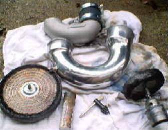 For
appearance, figured a bit of polishing would improve looks. The pipe was easy and maybe 25 minutes. Actually after doing the intake manifold and
cam cover … any other polishing projects are easy!!
For
appearance, figured a bit of polishing would improve looks. The pipe was easy and maybe 25 minutes. Actually after doing the intake manifold and
cam cover … any other polishing projects are easy!!
No need to sand this as a couple of different muslin cutting wheels and polishing rouges worked well enough. Will probably want to use at least a 6 amp drill so you can bear down with a few more groceries.
 May
as well add another 45 minutes and polish the turbo.
May
as well add another 45 minutes and polish the turbo.
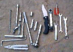 Kept
track of all the tools used for the install. Don’t recall all the sizes of wrenches and sockets used. The big nail was used as a drift pin to help
align and hold parts together during assembly. Ground the end of a cheapo $3.50 wrench to tighten a couple of manifold
bolts that were too awkward to reach using other tools
Kept
track of all the tools used for the install. Don’t recall all the sizes of wrenches and sockets used. The big nail was used as a drift pin to help
align and hold parts together during assembly. Ground the end of a cheapo $3.50 wrench to tighten a couple of manifold
bolts that were too awkward to reach using other tools
 Testing
the Vortech. Just did this for fun
since was planning to up the boost and using the BEGI AFPR. The unit indicated it was a 12:1, but acted
more like a 10:1 with undesirable quirks. Did not begin to raise any fuel pressure at all until a little over 1
PSI of boost. At about 5.25 PSI boost,
it appeared to completely clamp off the fuel return line and pegged the
pressure to gauge limit of 100 PSI with the Pierberg in-line pump
installed. Found the stock FPR and the
Vortech were completely invisible to the Pierberg while intake manifold was in
vacuum condition or vented to atmosphere.
Testing
the Vortech. Just did this for fun
since was planning to up the boost and using the BEGI AFPR. The unit indicated it was a 12:1, but acted
more like a 10:1 with undesirable quirks. Did not begin to raise any fuel pressure at all until a little over 1
PSI of boost. At about 5.25 PSI boost,
it appeared to completely clamp off the fuel return line and pegged the
pressure to gauge limit of 100 PSI with the Pierberg in-line pump
installed. Found the stock FPR and the
Vortech were completely invisible to the Pierberg while intake manifold was in
vacuum condition or vented to atmosphere.
My conclusion. The supplied Vortech works fine if planning to use the basic install and boost levels. Not worth throwing more money at it using a 6:1 kit. Start with a fully adjustable AFPR first prior to tinkering around with boost levels, changing fuel pumps, or hurting yourself with larger fuel injectors. This applies to using an AFPR based system and not if planning on using an aftermarket ECU
 Did
my testing by having the gauge on the fuel IN line back in “Prime Mode”
again. Spliced a boost/vacuum gauge
into the Mighty-Vac line directly into both the signal lines of the stock FPR
and the Vortech. Starting at 21hg
vacuum, vented it slowly to atmosphere and watched the stock FPR raise the fuel
pressure. Reversed the line on Mighty-Vac
to fake some boost pressure. Read the
boost gauge and watched the fuel pressure rise. Remember the Mighty-Vac only reads vacuum, so could have used
something like a bicycle pump for this portion of the simulation. Then taped the pressure gauge to outside of
windshield and found the readings were identical during an actual road test
with engine under load.
Did
my testing by having the gauge on the fuel IN line back in “Prime Mode”
again. Spliced a boost/vacuum gauge
into the Mighty-Vac line directly into both the signal lines of the stock FPR
and the Vortech. Starting at 21hg
vacuum, vented it slowly to atmosphere and watched the stock FPR raise the fuel
pressure. Reversed the line on Mighty-Vac
to fake some boost pressure. Read the
boost gauge and watched the fuel pressure rise. Remember the Mighty-Vac only reads vacuum, so could have used
something like a bicycle pump for this portion of the simulation. Then taped the pressure gauge to outside of
windshield and found the readings were identical during an actual road test
with engine under load.
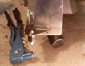 This
is an early heat shield (B Bowser) marketed by FM. Did not like the way it took the stress of connecting to the
engine one side and chassis on the other. Riveted the side tab a bit higher and added a little shock mount. Mr. Bowser added this feature to future
units.
This
is an early heat shield (B Bowser) marketed by FM. Did not like the way it took the stress of connecting to the
engine one side and chassis on the other. Riveted the side tab a bit higher and added a little shock mount. Mr. Bowser added this feature to future
units.
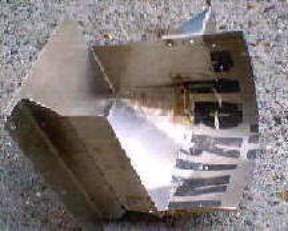 It
came stainless and was rather ill fitting. Had to push the brake valve back, lower brake lines, and hammer it to
get it to fit where I wanted. Used some
scrap metal to extend the back and rivet it in place. Had the pleasure of meeting Mr. Bowser, and assisted him a
little with design changes. Any ordered
now should be pure plug and play.
It
came stainless and was rather ill fitting. Had to push the brake valve back, lower brake lines, and hammer it to
get it to fit where I wanted. Used some
scrap metal to extend the back and rivet it in place. Had the pleasure of meeting Mr. Bowser, and assisted him a
little with design changes. Any ordered
now should be pure plug and play.
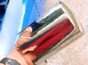 Had
this old chrome oil filter bouncing around in garage, so cut it to fit over the
brake fluid reservoir. Can get one from
JC Whitney for about $8. With the
reservoir and valves blanket wrapped, this fits down snugly over cup without
any rattle.
Had
this old chrome oil filter bouncing around in garage, so cut it to fit over the
brake fluid reservoir. Can get one from
JC Whitney for about $8. With the
reservoir and valves blanket wrapped, this fits down snugly over cup without
any rattle.
At first thought about using it to cover the charcoal canister, but the diameter was a bit too small.
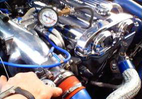
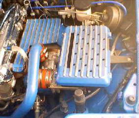
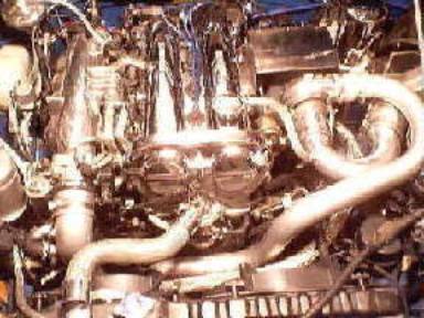 Here
is where we were in 2000. Would like to
think that some of these projects resulted in a fraction below 8 PSI boost even
with an intercooler installed. Notice
there is no larger downpipe, BOV, boost controller, turbo timer, aftermarket
ECU, or larger injectors. Am using the
Pierberg Pump, BEGI intercooler and AFPR, Bipes modified MSD, and after nearly 160 K miles still using the
original stock clutch. Exhaust is a
$119 Pacesetter cat-back with 2 ¼” plumbing. Using it for 8 years now without problems and ice and road salt is not a
problem here in Georgia. Notice the
small silver tab entering at an angle into the plumbing just below the TB. That is my nitrous fitting.
Here
is where we were in 2000. Would like to
think that some of these projects resulted in a fraction below 8 PSI boost even
with an intercooler installed. Notice
there is no larger downpipe, BOV, boost controller, turbo timer, aftermarket
ECU, or larger injectors. Am using the
Pierberg Pump, BEGI intercooler and AFPR, Bipes modified MSD, and after nearly 160 K miles still using the
original stock clutch. Exhaust is a
$119 Pacesetter cat-back with 2 ¼” plumbing. Using it for 8 years now without problems and ice and road salt is not a
problem here in Georgia. Notice the
small silver tab entering at an angle into the plumbing just below the TB. That is my nitrous fitting.
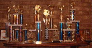 Self-serving
and shameless back patting! Unable to
stack more trophies on mantle due to limited space. A portion from an 8 year Miata collection. Have more of them sitting in closet.
Self-serving
and shameless back patting! Unable to
stack more trophies on mantle due to limited space. A portion from an 8 year Miata collection. Have more of them sitting in closet.