This is applicable to 1997 NA Miatas, but I believe that it should be correct for other NA year models and probably NB models.
Parts Required:
A) Switch panel - You can either use a blank switch panel from a Miata with manual windows or else cut a flat piece of sheet metal or plastic to fit and drill a few mounting holes to screw it to your console. If you opt to cut a new panel, I suggest making a template out of cardboard and once you've got the shape you want trace it on to the sheet metal or plastic that you plan to use. This might save you some frustration of getting the exact shape desired. Trace the area of the console cutout where the switches used to be onto your blanking plate. This will help you center the switches in the right place when you drill the plate.
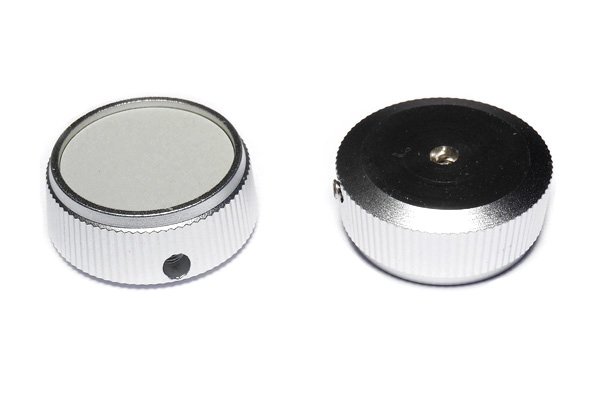
B) Switches - You will need two DPDT (double pole double throw) MOM.ON-OFF-MOM.ON switches. A DPDT switch will have SIX pins on the back. A momentary on/off/momentary on switch will have THREE positions, and will always return to the center position when not being pushed. You can use either a toggle or rocker switch type, but the toggle switches tend to be easier to mount (because they are inserted through a hole rather than a rectangular opening). You'll want to use a relatively heavy duty switch (ideally a 30A switch, but you can probably get away with a 25A or 20A switch) in order to prevent burning them out.
I used some switches from NAPA (p/n: ECH - TG7071). If you don't have any NAPA stores in your area, you want to look for something like this: http://www.parts-express.com/pe/show...number=060-376
C) Wire, spade connectors, crimpers - You'll need some basic electrical tools to hook everything up. I would recommend using at least 16-gauge wire, but 14-gauge wire might be better.
Wiring Up the Switches:
This is the most confusing part of the project for most people, but I will try to keep it simple.
You can either cut the pigtail off of an OEM window switch and adapt it to your new switches, or else you can use some standard male spade connectors to plug in the wires from your switches to the harness's power window connector.
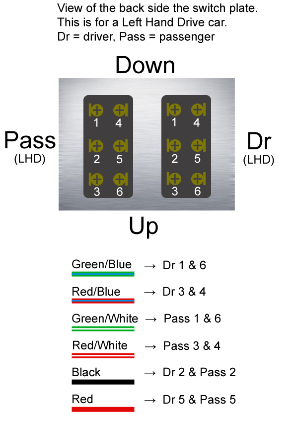
There will be 6 wires on the wiring harness's power window switch connector. If you are looking at the pinout for the OEM harness, what you see should be something like this:
______------______
|_B+W_|_G+R_|__R__|
|__B__|__G__|_R+G_|
The B+W wire is the 12v+ power source, the B wire is the ground. The G+R and G wires are the +/- for the driver side window, and the R and R+G are the +/- for the passenger window.
Each switch will have 6 pins (3 pairs of terminals-- top, middle, and bottom).
The first thing you need to do is split the B and B+W wires so that you have one of each going to both switches. You will connect these to either the top or bottom pair of terminals on the switches (depending on how much room you have where you are mounting the switch).
NOTE: These would be the BLACK and RED wires in the attached photos.
Next you will take some short lengths of wire and use them to jumper the top-left terminal to bottom-right terminal, and the top-right terminal to bottom-left terminal. It should look like an X across the back of the switch.
NOTE: These would be the BLACK and RED wires in the attached photos.
Now you just need to connect the signal wires for the power window motors to your switches. As mentioned before, the green and green+red wires are for the driver side window, and the red and red+green are for the passenger window. These will connect at the middle pairs of terminals.
NOTE: These would be the RED+WHITE and GREEN+WHITE wires for one switch and the RED+BLUE and GREEN+BLUE wires for the other switch.
The switches should now work properly, but you will want to test them out before putting everything back together. If something isn't right, take another look at these instructions and see if you can figure out where you went wrong. If all else fails, send me a PM and I will try to help you troubleshoot things to get it working properly.
Putting It All Together:
Once you're confident that the switches operate properly, mark your switch panel and drill your holes for mounting the switches. Be sure to take into account the size of the switches so that both switches fit into the panel and don't hit anything on the underside of the console.
* You may also consider using something like liquid electrical tape or silicon sealant to insulate the terminals on the back side of the switches if they are exposed. It's fairly unlikely that it could happen, but it would really suck to have them accidentally bump up against some bare metal somewhere along the transmission tunnel and short out.
Now just put it all back together. From here on out, you should be able to handle the rest of it without detailed instructions.
swichi01.jpgswichi02.jpgswichi03.jpgswichi04.jpgIMG_1420s.jpg8424_723274529999_11831309_41018806.jpgDSC_3337Large.jpg

 Reply With Quote