Wow, that is a ton of fab work, and all very nicely done.


Wow, that is a ton of fab work, and all very nicely done.

I feel so dirty after the first page. Bravo to you sir.

Incredible. Bravo, can't wait for more updates.

Ivd seen small write ups and pictures of your car, and I've always wanted an depth look on the fabrication and all the behind the scenes. Being a rotary and a roadster fan this is by far the best build ever. Motor mount design was fantastic, exhaust work as well. Cheers good sir.
etikoner (07-01-2014)

Originally Posted by Phatmiata
 Thanks Phatmiata. It's been a rather long project....been a few twists and turns along the way. As you've probably gathered, I'm posting these build updates retrospectively, so there is still a few hundred more photos to post
.
There will definitely be some videos once we've got the engine running.
The cutting of the bonnet was done with multiple tools...a drill, an air-hacksaw, a blending wheel and a little bit of skill. :-)
Regards,
Danny
Phatmiata (07-01-2014)
Thanks guys. I'll try and get the updates posted up to where the build is currently by weeks end. I'm glad that you're enjoying the build write-up.
Regards,
Danny
Phatmiata (07-01-2014)
Actual work on the car has slowed down in the last few weeks...that's not saying that nothing is happening at all. As previously mentioned, the engines rotating assembly is away being balanced. I hope to have it back this week so that assembly can begin either late next week or early the week after.
In the mean time progress on the wiring has gone forward in leaps and bounds. A whole new loom is being made for the car to simplify the electrical system and to remove any unneccessary wiring loom sections and electrical components.
Where OEM electrical components are being re-used, short loom tails were terminated and plugged.
This is the main chassis loom. Once layed out in the car it will be shortened and terminated accordingly.
The coil bracket has also been completed....and yes the backing plate was welded on back to front!I'll knock another one up before the car is finished.
I've also spent some time drawing up the mount assembly for the Motec M800, Motec PDM15 and the two M&W Pro-16's. I'm still to finalise the attachment of the assembly on the firewall above the passenger side footwell. This will be done once I've got the whole lot together and physically in the car.
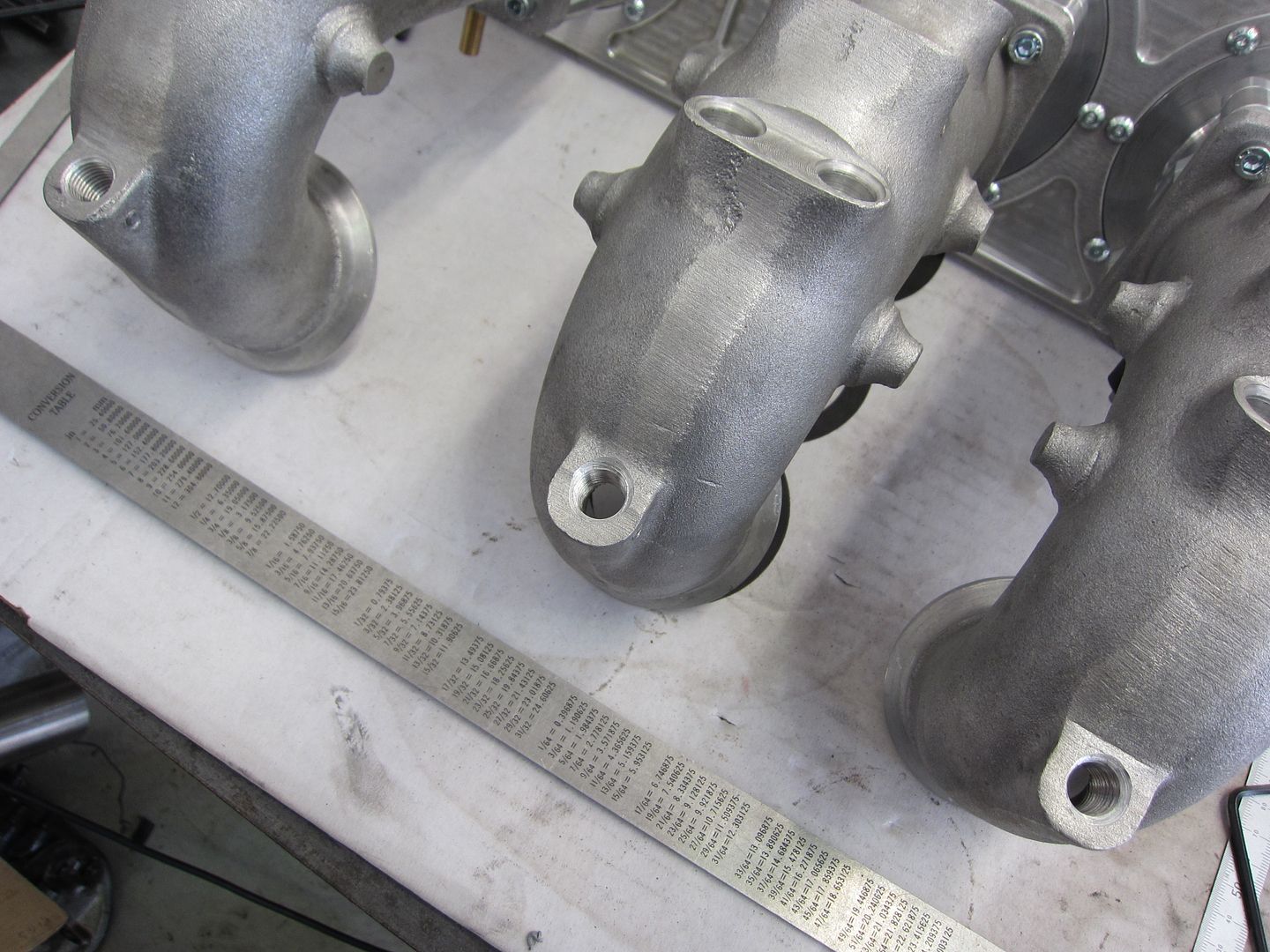
Time has also been put into the cooling system take-off point at the front of the engine (where the OEM water pump and thermostat housing once resided).
The fittings are dash 16 and provision has been made for the following sensors.
(1) Coolant Inlet Temp - Motec datalogger
(2) Coolant Outlet Temp - Motec datalogger
(3) Coolant Outlet Temp - Defi Gauge (for redundancy)
(4) Cooling System Pressure - Motec datalogger
With the sensors, fittings and fasteners in position.
I'm still inching along at the moment by sorting out some minor details.
To suit the shorter ID1000 fuel injector length I had to redesign the fuel rail restraint brackets.
...and I started assembling the throttle linkages.
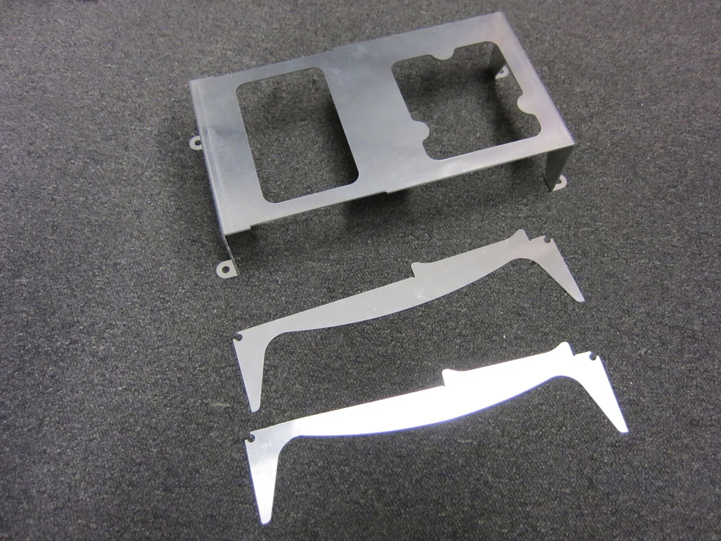
Another minor detail which is more about presentation than anything else were the blanking plates for the no-longer-required side ports. The side ports will be filled with Devcon prior to engine assembly.
The laser cut components for the mount assembly also arrived this week all pressed and ready for welding.
Phatmiata (07-01-2014)
Ta-da!
The fun part will getting the mounting on the firewall about the passenger footwell.
The first part of the wiring loom install was undertaken with the fitting of the plate and bulkhead fittings to the firewall.
To give more room for the looms as they extend out into the engine bay I've relocated the coil bracket assembly. This will tidy the engine bay up quite a bit.
The last thing done this week was the removal of the windscreen wiper motor assembly that once resided here.There's a couple of kg's in that!
Engine build time!!!
In mid-November all the engine components returned from having their various modifications done (such as machining and balancing).
The inlet and exhaust ports in the rotor housings had their final machining and hand finishing completed. Man these are huge!!!
To improve heat transfer in the "hot" area (between the spark plugs and the exhaust port) of the rotor housings, a series of grooves were machined in the water galleries to increase coolant to alloy surface area. This has been long used by Racing Beat in the US to minimise localised dimensional change of the rotor housing in the "hot" area.
...as mentioned earlier, to minimise this risk even further, post radiator coolant will be delivered at the two additional ports machined adjacent to each of the spark plug holes.
The rotors have all been lightened, side clearanced and balanced to 10,000rpm.
....but there is one last job that has to be done before the engine can be assembled.
So the last thing to do before being able to finally assemble the engine was to block off the all the side inlet ports that are no longer required.
The perfect material for the task is Devcon Plastic Steel Putty. At around $130 for 500g it's not cheap, especially when I need to fill six rather large inlet ports!
So here's the process.....combine the two components.
Stir away until it is properly mixed together.
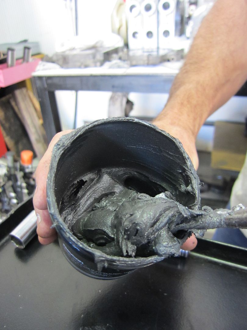
Then start filling the ports as quickly as possible before it hardens up!
Then repeat five more times....
And done!
It's finally time to assemble the engine.....well at least the core.
The rotors were lightened, side clearanced and balanced to ensure the engine is vibration free all the way up to 10,000rpm.
Each of the 18 side seals were then clearanced to suit their respective grooves.
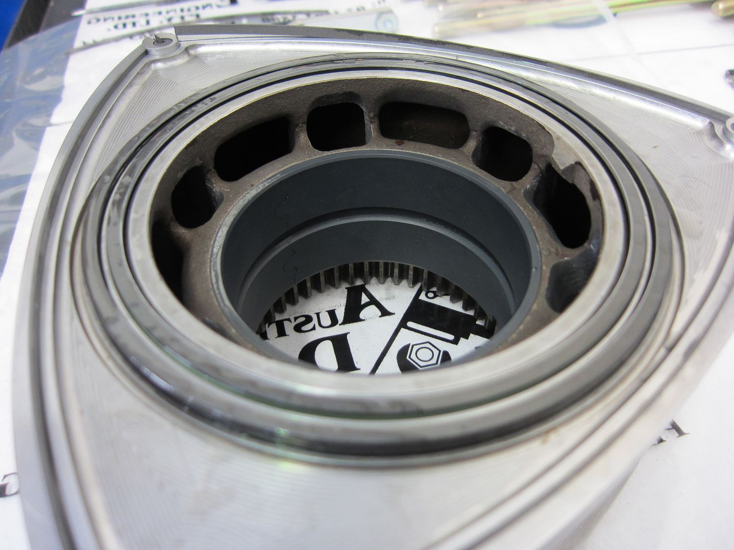
This is a rather rare item (well NLA new)...the centre stationary gear from the "Thick" plate. It has had a new bearing (also NLA) installed.
The front and rear stationary gears also scored a new bearing each and a rear main seal.
The through bolts were zinc plating.
Now this is a really neat modification....the addition of an 'O'-ring groove in the front plate where the oil pump mounts. Normally the oil pump is bolted here just as a metal to metal seal. However, as you increase the oil relief pressure the sealing surface has been known to be breached resulting in a loss of all pressure to the rest of the engine. The addition of an 'O'-ring to this mating face ensures that no oil pressure is lost at elevated oil pressure. You can that the oil pump galleries have also been ported and polished to improve oil flow.
The plates also got a lick of paint. 8)
The oil control rings in each rotor were then installed.
Phatmiata (07-01-2014)
Beside the rotors the only other moving part is the eccentric shaft. In 20B engines they are two piece so that the engine can be assembled. It has also been isotropically finished. More info here http://xtremerotaries.com/services/i...superfinishing
This is the custom front pulley that will drive the dry sump scavange pump and alternator.
The Iannetti 'Gold' apex seals and spring assemblies.
Starting at the "Thick" plate the first rotor was positioned.
Eccentric shaft in place.
Rotor housings ready to go.
First rotor housing positioned and apex seals going in.
First chamber sealed.
Second rotor in position.
Rotor housing in place.
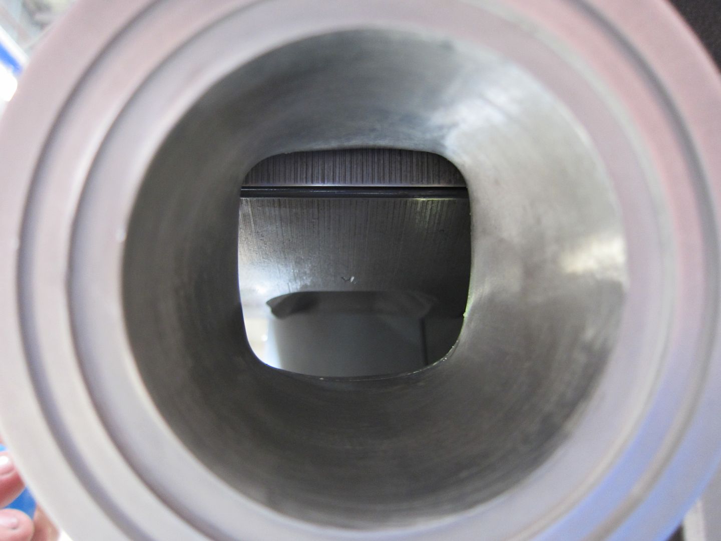
A couple of sneaky port shots...
Apex seals fitted.
...and sealed.
Time to flip the engine over and add the last rotor housing.
Last rotor in position.
Last rotor housing in place.
Apex seals in....
....and sealed. 8)
So that's the engine core assembled. There's still a whole lot of ancillaries that are yet to be attached.
So continuing on with the engine assembly....the oil pump and front counterweight assemblies were installed.
Main oil gallery 'O'-ring...things get rather expensive if you don't install in properly or there is an act of god and it fails! :evil:
Inlet and exhaust ports temporarily sealed.
Rear stationary gear and counterweight fitted.
In preparation for the dry sump to be installed.
Clutch and flywheel assembly fitted.
Dry sump and front cover bracket fitted.
Front pulley installed and bolt torqued.
All three rotor housing supplementary coolant delivery blocks installed.
Alternator on.
The engine ready to be dropped back into the chassis for the second last time....but the last time before it will finally run. 8)
The chassis with dummy engine removed awaiting the new engine.
Cheers,
Danny
First was bolting the freshly assembled engine back in the car. 8)
I'm really happy with where the engine is positioned in the chassis.
Thought I'd fit up the toothed drive belt for the alternator and dry sump scavenge pump(s).
As previously shown this was the water take-off assembly I'd designed for use on the engine. After trying numerous machine shops I wasn't able to get a one-off done for a price that met my budget.
The good news was that Xtreme Rotaries had just released a similar product right before Xmas at a very good price (even though it doesn't have any sensor ports) so I ordered one straight away. The sensors can easily be positioned in other locations in the engine cooling system.
Nice detail - 'O'-ring groove instead of the OEM paper gasket. 8)
The OEM water pump housing attachment flange all ready to receive the new take-off assembly.
...and fitted.
...with the -20 fittings installed.
Next was fitting of the front and mid-sections of the exhaust system with new OEM and custom gaskets.
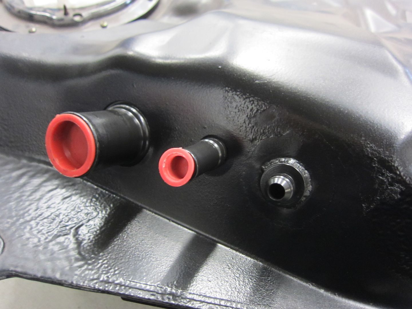
...but before I fitted the exhaust mid-sections I took the opportunity remove the fuel tank so that a fitting for a fuel return line could be added because in standard form the NC uses a return-less fuel system.
The row of bulkhead fittings that go between the boot cavity and the underbody.
With the NC only seeing 3,000km before it was totalled, there wasn't too much opportunity for contamination and with the last time it was filled up being in early 2006, there was no chance of even a whiff of fuel.
The extra fitting welded on.
...and done!
These are the custom exhaust gasket I has made for the 6-bolt flanges.
Mid-sections installed.
Some of the off-the-car work I did was on the following items.
Single Injector plug clamp bracket.
Adaptor flange for the crankcase breather line on the intermediate plate (previously the oil filler neck).
Adaptor block that allows the fitment of an RX-8 starter motor. Mounts where the OEM 20B starter motor once mounted.
Custom oil distribution block to suit the RX-8 clutch slave cylinder and NC firewall.
Dash 20 fittings are huge! These are just a couple I'm using for testing....the real ones will be black.
Since New Years day most of my effort has been in working through options for the ducting the cooling air through the heat exchangers (engine coolant and engine oil) and integrating it into the front splitter/diffuser.
The front bar has been split to facilitate the much lower splitter height I can run in accordance with WTAC open class rules.
The two heat exhangers are custom PWR units built to my dimensional specifications.
Getting a feel for the position.
This is just a concept at the moment as there's heaps more dimensions I need to confirm and give consideration to other items that need to be mounted.
Cheers,
Danny
There's been some good progress in design, manufacturing and assembly over the past week or so.
Starting with design...most effort has been put into the heat exchanger assembly which integrates with the front splitter/diffuser. I don't think I've put up up photos of the engine coolant radiator and engine oil cooler. So here they are.
So basically the concept is that the two heat exchangers are welded together to form an air tight box that is part of the ducted cooling air system. A Spal thermo-fan is also included to provide air flow whilst the vehicle is stationary or has low road speed.
Materials for the above and the rest of the ducted air system (below) should be ordered this week.
Manufacturing wise, the following has been completed.
Adaptor flange for the crankcase breather line on the intermediate plate (previously the oil filler neck).
...and installed.
The adaptor to mount the RX-8 starter motor. Just needs to be drilled and tapped with a bell housing bolt thread once measured.
Trial fitting on the dummy block.
The mounting bracket for the Motec C125 dash logger.
...and finally assembly.
The inlet manifold and throttle linkage assembly has been completed. This includes the TPS unit.
The inlet manifold runners have also been drilled and tapped for the vacuum take-off points.
ueru (07-01-2014)
The inlet manifold finally back on the engine. 8)
A different clutch slave cylinder was sourced to provide better clearance to the oil take-off block that resides on the rear plate.
So here she is pushed back to the fab corner awaiting the supply of materials for the front splitter/diffuser and ducted cooling air system.
Some of the processed materials for the front splitter/diffuser and ducted cooling air system arrived late yesterday.
In anticipation I grabbed the two heat exchangers from my office.
The items that required rolling and pressing were completed first. They were the upper and lower panels of the inlet duct. This is the lower with rolled edge.
This is the pressed upper panel.
The completed upper and lower panels.
I employ mortise and tenon quite a bit when I design. It's effectively self-jigging and reduces fabrication error. You can see the tenons in the below photo.
This is one of the side plates with the mortises.
Connecting the upper and lower panels to the side plates.
Tack welding the assembly.
The pinch weld was then trimmed to length and trial fitted. Pinch weld is used to minimise leakage of cooling air from the duct.
I'm very, very happy with the outcome!
The next fabrication job is to build the heat exchanger assembly unit (joining the coolant radiator and oil cooler together).
Design of the mounting bracket assembly for the electric water pump has continued.
Cheers,
Danny
 Posting Permissions

 Reply With Quote


