-
3,000 rpm - starting to feel the power


-
The Following User Says Thank You to hoodedreeper For This Useful Post:
Agent☣Orange (04-11-2022)
-
3,000 rpm - starting to feel the power
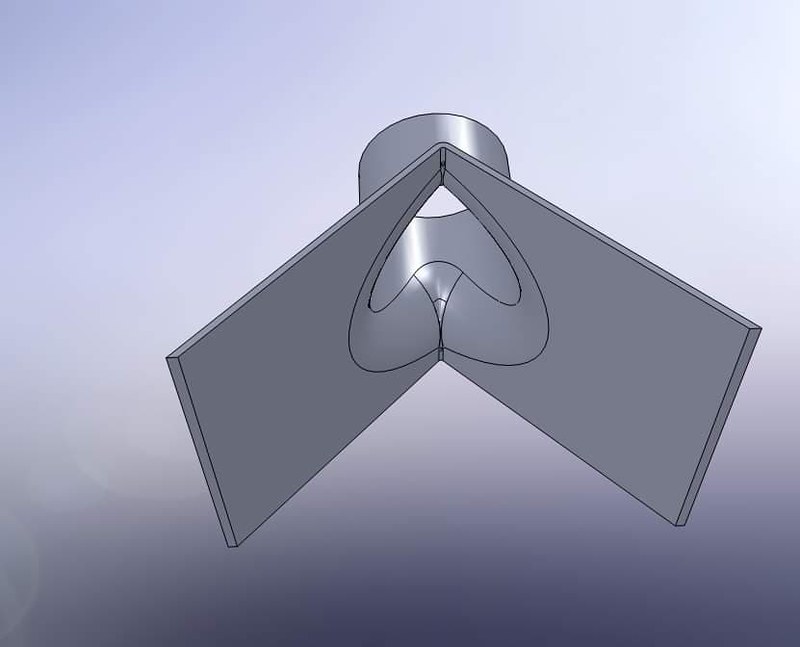
The next bright idea I had was to carry on with the fog light duct idea, but this time use them for brake ducts. I called upon my friend Paul who is very knowledgable when it comes with making things from scratch, and hes a dab hand at 3D modelling. I gave him some dimensions and explained the idea and he got to work. A day later he sends me these...

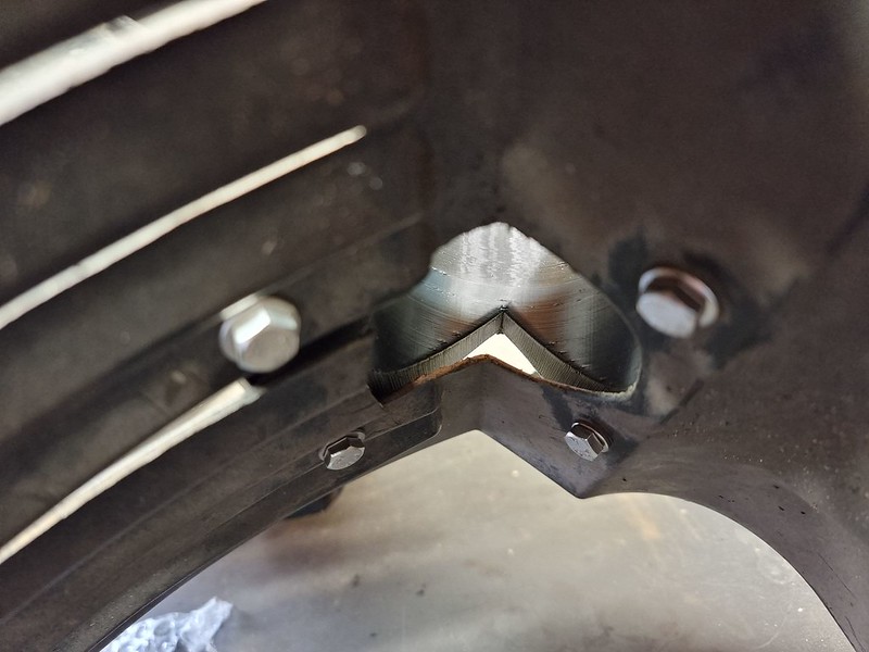
With the vents trimmed it was time to mark the arch liners and get drilling. Annoyingly my holesaw was about 3-4mm too small but that shouldn't matter too much. I under estimated the angle of the arch liner, so the vents aren't a snug fit as I had hoped, leaving a gap between the two surfaces

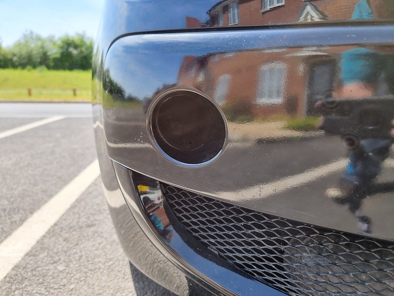
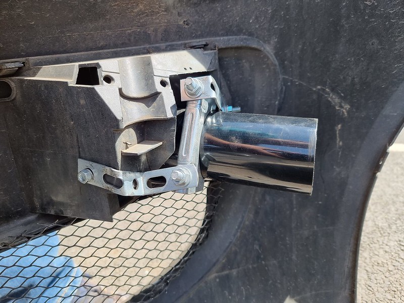
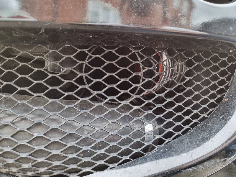
Next my attention was turned to the inlets on the bumper. I purchased some 68mm uPVC tubing and cut them down to the desired length, also cutting one end at a sharp angle to help follow the curve of the bumper
Now, behind the bumper isn't the tidiest,prettiest or the best solution. But if it works it works, it only needs to hold the weight of the tubing. I used an exhaust clamp and dexion strip to hold them in place.
The next hurdle was to tackle what was behind the bumper. In the case of the driver side the gigantic windscreen washer bottle covers the height and almost the width of the arch liner area. There was absolutely no way that any duct hose was going to get past this and to the bottom corner. So that had to go. Luckily for me, I sell a universal washer bottle kit at work which should do the job. With a pair of rivnuts now secured into the chassis rail and the bracket fixed on, the bottle slides on and now gives ample amount of room. The filler cap is accessable from the engine bay,although I'll need to use a flexy funnel to refill.

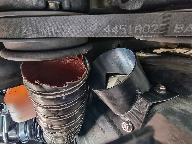
Things were going too smoothly, now it was time to throw a spanner in the works. It turns out I never paid attention to the direction of the arch liner vent. With the arch liner now refitted, I found out the vent points directly at the drive belt pulley face palm

I got back in contact with Paul and he remodelled the duct, printed it and sent it out super fast.
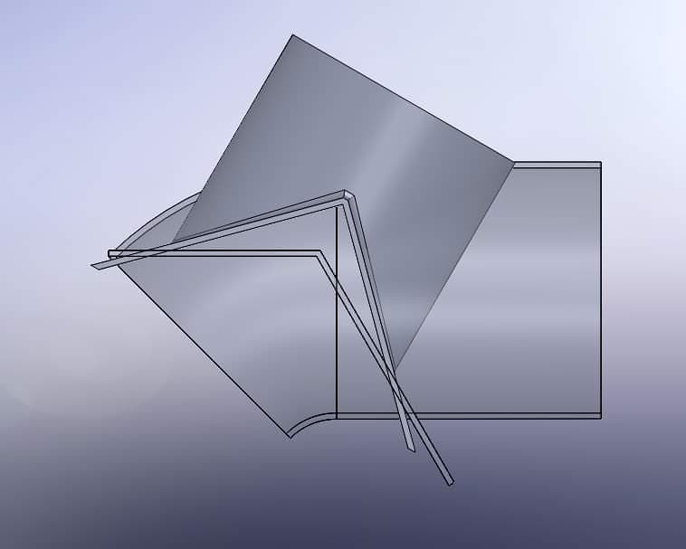
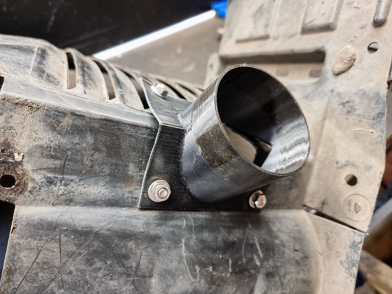
He increased the angle to hopefully match the true angle of the arch liner. Along with the change of inlet angle he also made it so it protrudes into the arch itself

With the arch liner centre hole enlarged and new mounting holes drilled it was time to see if v2 was a success. The cutting isn't the neatest which I'm disappointed about, but it can't be helped now.
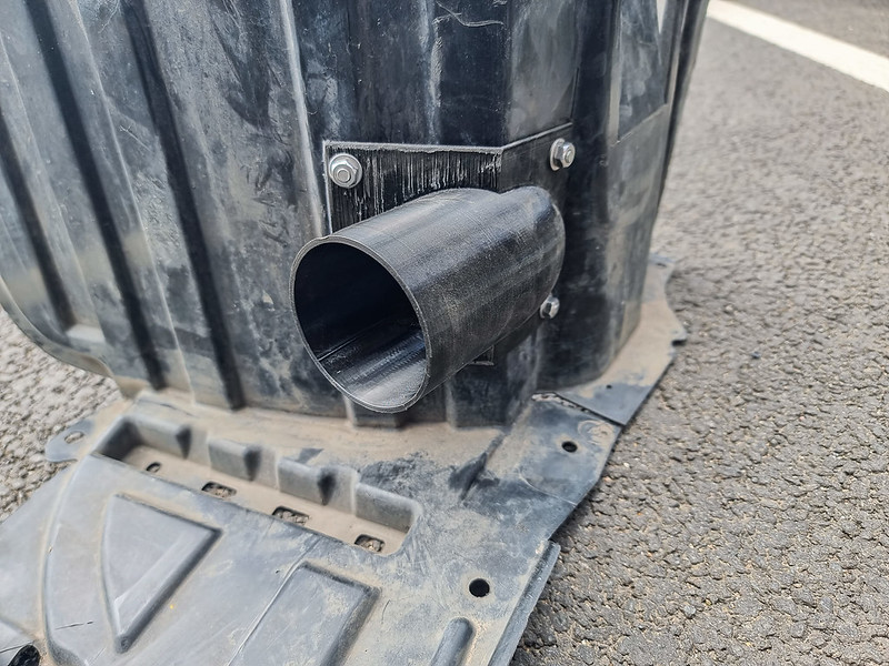

Woohoo! It fits!

So with the driver side now finally finished, the passenger side should be a breeze! Shouldn't it?... Turns out the intercooler pipe is directly behind the bumper inlet. To get around this I used another piece of the uPVC tubing and attached it above the intercooler hard pipe in the lower grill of the bumper. Not ideal, but without changing that side of the Intercooler pipe work completely, it's the only way.
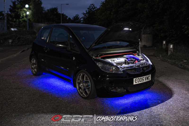
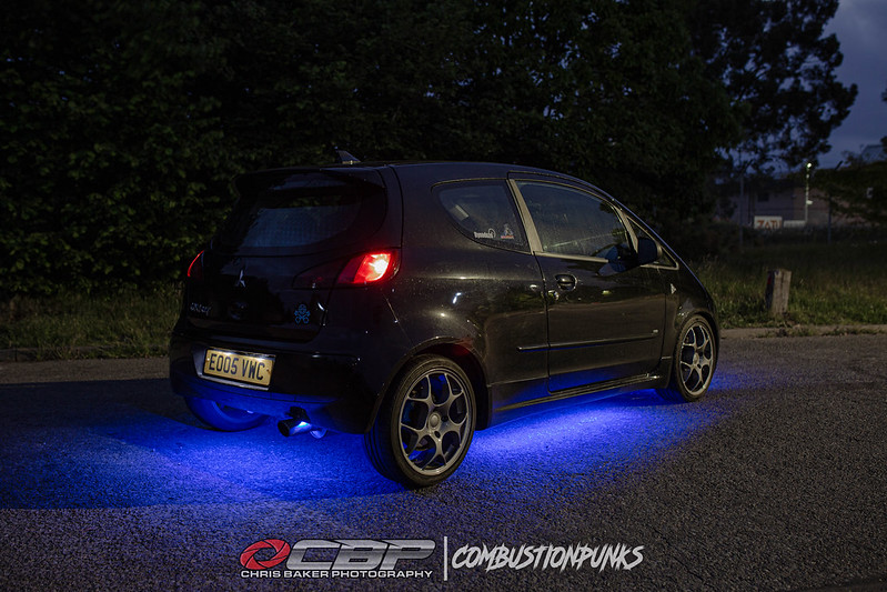
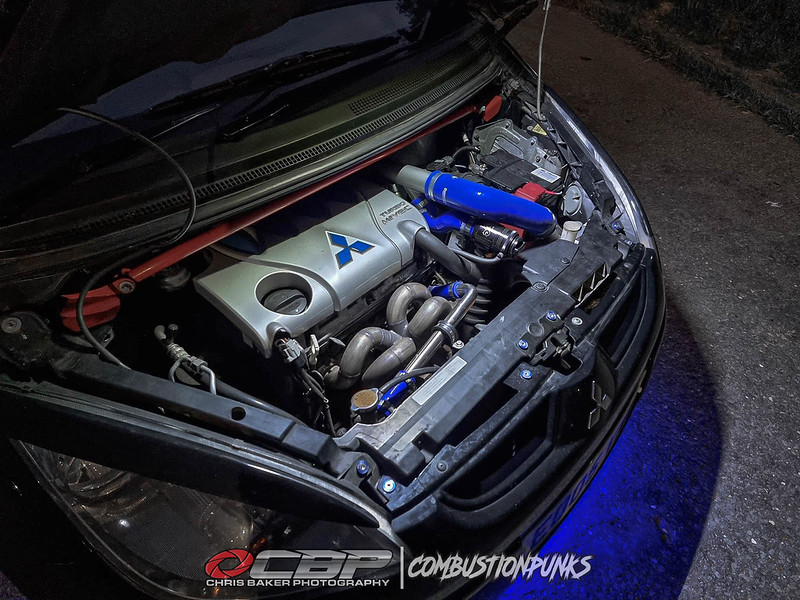
I do have a Youtube video for this, but it's currently being edited so I'll add it once its uploaded The final installment of this big update is a modification that is world wide regarded as VERY marmite, some like it, alot don't haha UNDER GLOW! I can sense you're all just sighing loudly,resting your face in your hands shaking your head at the screen. It wouldn't be a nod to the Max Power era if the car didn't have it I started by feeding the power cables through the bulk head and completing majority of the wiring inside the car before I started underneath. Full details are in the Youtube video (link at the end)

I also installed an under bonnet light,feeding the wiring through the bonnet skin and through the bulk head. The sound deadening needs tidying up but its presentable for now

I had access to a four poster ramp to allow me to underseal the centre of the car and to fit the underglow. Unfortunately due to the other vehicles in the unit, I was limited to hand brushing the underseal on. This is before, quite clean to be fair. The areas were wire brushed down followed by a coat of Kurust before the underbody seal.
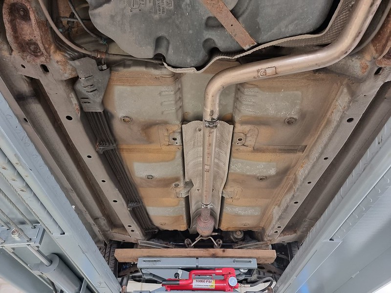
The main areas sealed. The harder to reach areas will be aerosol'd at a later date
[img]https://live.staticflickr.com/65535/52132396868_dc46cc7665_c.jpg[/img


Also done the majority of the rear axle too. When the wheels are next off I'll finish those areas


https://www.youtube.com/watch?v=uRSkPrq1fg8
Since the video I've added an in-line fuse on the positive battery lead for the fuse box, along with moving back the front LED strip to hopefully make it less visible.
And there we have it, I apologise again for the lengthy read
-
The Following 2 Users Say Thank You to hoodedreeper For This Useful Post:
Agent☣Orange (06-13-2022),MaRcOp01o (06-09-2022)
 Posting Permissions
- You may not post new threads
- You may not post replies
- You may not post attachments
- You may not edit your posts
-
Forum Rules


 Reply With Quote